52
Timing, IRIG-B and Pulses
8.3.2
Modulated and Unmodulated IRIG-B
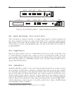
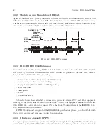
Figure 8.2 illustrates the primary differences between modulated and unmodulated IRIG-B. You
will notice that the while modulated IRIG-B is distinctive because of the 1 kHz sinewave carrier,
it is similar to unmodulated IRIG-B since the peak-to-peak values of the carrier follow the same
form as the peaks of the digital waveform, which contain the information.
ON-TIME 1 PPS
IRIG
B003
B004
REFERENCE
REFERENCE
IRIG ZERO
IRIG
B123
B124
IRIG ONE
Start of next
second in
time code
MODULATED
UNMODULATED
Figure 8.2: IRIG-B Waveforms
8.3.3
IRIG-B IEEE 1344 Extension
As mentioned above, the turning IEEE 1344 ON in the clock enables extra bits of the Control
Function (CF) portion of the IRIG-B time code. Within this portion of the time code, bits are
designated for additional features, including:
•
Calendar Year (old method, now called
BCD
Y EAR
)
•
Leap seconds, and leap seconds pending
•
Daylight Saving Time (DST), and DST pending
•
Local time offset
•
Time quality
•
Parity
•
Position identifiers
To be able to use these extra bits of information, protective relays, RTU’s and other equipment
receiving the time code must be able to decode them. Consult your equipment manual to determine
if the IEEE 1344 feature should be turned ON in the clock. To view details of the IEEE Std 1344-
1995, please check with the IEEE.
NOTE
: To download a copy of of the IRIG-B 2004 specification, please go to the Arbiter web
site (at www.arbiter.com) and check under Documentation.
8.3.4
1 Pulse-per-Second (1 PPS)
A one pulse-per-second timing signal is very simple in concept. It is a digital bit transmitted every
second with a pulse width of 10 milliseconds. A critical part of this signal is that it is “on time” at
Содержание 1092A
Страница 4: ...iv ...
Страница 18: ...xviii LIST OF TABLES ...
Страница 129: ...C 10 Option 20A Four Fiber Optic Outputs 111 Figure C 7 Option 20A Jumper Locations ...
Страница 131: ...C 11 Option 27 8 Channel High Drive 113 Figure C 8 Option 27 Jumper Locations ...
Страница 148: ...130 Options List Figure C 10 Option 29 Connector Signal Locations ...

