Chapter 8
Relay Contacts and Event Inputs
8.1
Relay Contacts,
by Option
Model 1088B can supply relay contacts through installation of an optional accessory. Option 19
provides one Form C (SPDT) set of contacts that can be used for the Out-of-Lock function. Option
29 provides four additional timing outputs and has two solid-state relays available with output
multiple functions and +25/50 Vdc supplies. For additional information on relay specifications and
operation, please see Option 19 in Section C.15, and Option 29 in Section C.20.
8.2
Event Inputs
8.2.1
Event Timing Input
When configured for event timing, the 1088B can provide two input channels with 0.1 microsecond
resolution. These two channels are called Event A and Event B. Event A is primarily used for
synchronization via the RS-232 port with an external computer or other type of device. It may
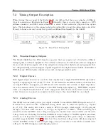
also be used to time an external 5 V CMOS signal applied to J4; see Figure 5.1 and Section 5.2.2.
Event B may only be applied to J3 and must be a 5 V CMOS signal.
Data for individual recorded events can be recalled using either the Event/Deviation key or via the
RS-232C interface (see Section 9.2.2). Data for each event will be retained until it is retrieved using
one of these two methods. Thus, if no event data points are retrieved, recording will be suspended
when the total number of events per channel reaches 200. As soon as data is retrieved for a recorded
event, its address (001 - 200) is made available for data corresponding to a new incoming event.
8.2.2
Event Timing Latency
Event data are recorded using a high-speed capture circuit operating with a 4 MHz time-base.
Latency is limited by the interrupt processing speed of the clock’s microcontroller, which in turn
depends on its workload at the time the event is received. Since the workload varies from time
to time, latency likewise varies. However, response time will, in general, never be less than a few
hundred microseconds nor greater than 10 milliseconds.
Содержание 1088A
Страница 4: ...iv ...
Страница 6: ...vi ...
Страница 18: ...xviii LIST OF FIGURES ...
Страница 23: ...1 4 Attaching Rack Mount Ears to 1088A B Series Clocks 3 Figure 1 2 Attaching Rack Mount Ears ...
Страница 24: ...4 Unpacking the Clock ...
Страница 32: ...12 Front and Rear Panels ...
Страница 38: ...18 Connecting Inlet Power Input and Output Signals ...
Страница 41: ...4 1 GPS Antenna Installation 21 Figure 4 2 Antenna Mounting Bracket Figure 4 3 Antenna Mounting with AS0044600 ...
Страница 46: ...26 GPS Antenna and Cable Information ...
Страница 48: ...28 Setting Internal Jumpers Figure 5 1 Model 1088B Main Board ...
Страница 76: ...56 The Setup Menus ...
Страница 112: ...92 Serial Communication and Command Set ...
Страница 127: ...B 4 Physical Dimensions 107 Figure B 1 Suggested Mounting of the AS0094500 Surge Arrester ...
Страница 128: ...108 Using Surge Arresters ...
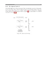
Страница 137: ...C 5 Option 04 Parallel BCD Output 117 C 5 2 Option 04 Firmware Setup Figure C 2 Option 04 Firmware Setup ...
Страница 145: ...C 5 Option 04 Parallel BCD Output 125 Figure C 4 Option 04 Output Jumper Settings ...
Страница 146: ...126 Options List Figure C 5 Option 04 Board Layout and Jumper Locations ...
Страница 165: ...C 12 Option 17 Parallel BCD Output and Second RS 232 Port 145 Figure C 11 Option 17 Output Jumper Settings ...
Страница 166: ...146 Options List Figure C 12 Option 17 Board Layout and Jumper Locations ...
Страница 176: ...156 Options List C 14 5 Typical Network Configuration Figure C 15 Option 18 Network Configuration ...
Страница 187: ...C 16 Option 20A Four Fiber Optic Outputs 167 Figure C 22 Option 20A Jumper Locations ...
Страница 194: ...174 Options List Figure C 24 Option 23 Internal Jumper Setup ...
Страница 196: ...176 Options List Figure C 25 Option 27 Jumper Locations ...
Страница 214: ...194 Options List Figure C 28 Option 29 Connector Signal Locations ...
Страница 270: ...250 Options List ...


