Chapter 5
Setting Internal Jumpers
5.1
Introduction
Jumpers in the the 1088B series clocks are already set up at the factory according to the purchase
order. If it should be necessary to change any jumpers or to enable any new function, you should
follow the instructions in this section.
This section should assist you with understanding and setting the internal main board jumpers in
the Model 1088B. After correctly setting the necessary jumpers, go to Chapter 6, The Setup Menu,
for details on how to configure these signals from the front panel keys. Most settings may also be
configured through the RS-232 port. If you wish to know additional technical details about timing
signals, please see Chapter 7, Timing, IRIG-B, and Pulses.
NOTE:
Values in tables marked with an “*” show default positions.
5.2
Changing Hardware Settings Via Internal Jumpers
The 1088B incorporate a flexible input and output (I/O) selection system, which is made possible
by an innovative internal jumper scheme. Each of the four, standard, rear-panel I/O connectors
can be reconfigured to perform any of the available output functions. Alternatively, any or all of
the I/O connectors can be set to act as an input to the 1088B. However, each of the I/O connectors
is assigned only one specific and exclusive input function.
Besides configuring the four main output connectors, there are other settings that will be explained
in this section. These include whether to use the RS-232 port or one of the standard I/O connectors
for event input signals, setting the frequency reference for the clock, and setting the battery-backed
RAM.
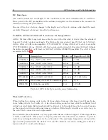
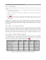
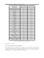
When changing any of the jumpers you will want to refer to the main board layout diagram in
Figure 5.1 to locate jumper positions. Tables 5.1, 5.2 and 5.3 will also help to identify meanings
to the various settings.
Содержание 1088A
Страница 4: ...iv ...
Страница 6: ...vi ...
Страница 18: ...xviii LIST OF FIGURES ...
Страница 23: ...1 4 Attaching Rack Mount Ears to 1088A B Series Clocks 3 Figure 1 2 Attaching Rack Mount Ears ...
Страница 24: ...4 Unpacking the Clock ...
Страница 32: ...12 Front and Rear Panels ...
Страница 38: ...18 Connecting Inlet Power Input and Output Signals ...
Страница 41: ...4 1 GPS Antenna Installation 21 Figure 4 2 Antenna Mounting Bracket Figure 4 3 Antenna Mounting with AS0044600 ...
Страница 46: ...26 GPS Antenna and Cable Information ...
Страница 48: ...28 Setting Internal Jumpers Figure 5 1 Model 1088B Main Board ...
Страница 76: ...56 The Setup Menus ...
Страница 112: ...92 Serial Communication and Command Set ...
Страница 127: ...B 4 Physical Dimensions 107 Figure B 1 Suggested Mounting of the AS0094500 Surge Arrester ...
Страница 128: ...108 Using Surge Arresters ...
Страница 137: ...C 5 Option 04 Parallel BCD Output 117 C 5 2 Option 04 Firmware Setup Figure C 2 Option 04 Firmware Setup ...
Страница 145: ...C 5 Option 04 Parallel BCD Output 125 Figure C 4 Option 04 Output Jumper Settings ...
Страница 146: ...126 Options List Figure C 5 Option 04 Board Layout and Jumper Locations ...
Страница 165: ...C 12 Option 17 Parallel BCD Output and Second RS 232 Port 145 Figure C 11 Option 17 Output Jumper Settings ...
Страница 166: ...146 Options List Figure C 12 Option 17 Board Layout and Jumper Locations ...
Страница 176: ...156 Options List C 14 5 Typical Network Configuration Figure C 15 Option 18 Network Configuration ...
Страница 187: ...C 16 Option 20A Four Fiber Optic Outputs 167 Figure C 22 Option 20A Jumper Locations ...
Страница 194: ...174 Options List Figure C 24 Option 23 Internal Jumper Setup ...
Страница 196: ...176 Options List Figure C 25 Option 27 Jumper Locations ...
Страница 214: ...194 Options List Figure C 28 Option 29 Connector Signal Locations ...
Страница 270: ...250 Options List ...


