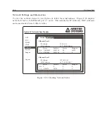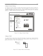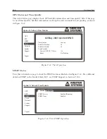
C.19 Option 34: NTP/PTP Server
191
PTP Configuration
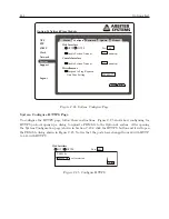
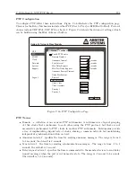
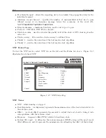
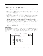
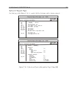
To configure PTP follow these instructions. Figure C.36 illustrates the PTP configuration page.
Choices for the Delay Mechanism include either P2P (Peer to Peer) or E2E (End to End). Protocol
choices include UDP IPv4, UDP IPv6 or Layer 2. Figure C.36 shows the Advanced settings, which
can be hidden using the Hide Advanced button.
Option 34 Network Time Module
Status
Configure
NTP
SNMP
Clock
Network
System
Support
Logout
PTP
Enable PTP Service
Apply
Reset
Domain Number
Announce Interval
Sync Interval
Min Delay Request
Min Peer Delay Request
Announce Receipt Timeout
Delay Mechanism
Protocol
Clock Class
Clock Accuracy
Priority 1
Priority 2
0
2
2
2
2
3
P2P
UDP IPv4
6
20
10
128
Hide Advanced
seconds
seconds
seconds
seconds
Figure C.36: PTP Configuration Page
PTP Terms
•
Domain – a collection of one or more PTP subdomains. A subdomain is a logical grouping
of 1588 clocks that synchronize to each other using the PTP protocol, but that are not
necessarily synchronized to PTP clocks in another PTP subdomain. Subdomains provide
a way of implementing disjoint sets of clocks, sharing a common network, but maintaining
independent synchronization within each set.
•
Announce interval – specifies the time for sending announce messages. The range is from 0
to 4 seconds; the default is 2 seconds.
•
Sync interval – the time for sending synchronization messages. The range is from -1 to 1
seconds; the default is 1 second.
•
Delay request interval – specifies the time recommended to the member devices to send delay
request messages when the port is in the master state. The range is -1 second to 6 seconds.
The default is 5 (32 seconds).
Содержание 1084A
Страница 4: ...iv ...
Страница 6: ...vi ...
Страница 18: ...xviii LIST OF FIGURES ...
Страница 23: ...1 4 Attaching Rack Mount Ears to 1084A B C Series Clocks 3 Figure 1 2 Attaching Rack Mount Ears ...
Страница 24: ...4 Unpacking the Clock ...
Страница 36: ...16 Connecting Inlet Power Input and Output Signals ...
Страница 39: ...4 1 GPS Antenna Installation 19 Figure 4 2 Antenna Mounting Bracket Figure 4 3 Antenna Mounting with AS0044600 ...
Страница 44: ...24 GPS Antenna and Cable Information ...
Страница 114: ...94 Startup and Basic Operation ...
Страница 123: ...B 4 Physical Dimensions 103 Figure B 1 Suggested Mounting of the AS0094500 Surge Arrester ...
Страница 124: ...104 Using Surge Arresters ...
Страница 134: ...114 Options List C 6 2 Option 06 Firmware Setup Figure C 3 Option 06 Firmware Setup ...
Страница 142: ...122 Options List Figure C 5 Option 06 Output Jumper Settings ...
Страница 143: ...C 6 Option 06 Parallel BCD Output 1 millisecond Resolution 123 Figure C 6 Option 06 Board Layout and Jumper Locations ...
Страница 157: ...C 10 Option 17 Parallel BCD Output and Second RS 232C Port 137 Figure C 12 Option 17 Output Jumper Settings ...
Страница 158: ...138 Options List Figure C 13 Option 17 Board Layout and Jumper Locations ...
Страница 163: ...C 13 Option 20A Four Fiber Optic Outputs 143 Figure C 14 Option 20A Jumper Locations ...
Страница 170: ...150 Options List Figure C 16 Option 23 Internal Jumper Setup ...
Страница 172: ...152 Options List Figure C 17 Option 27 Jumper Locations ...
Страница 190: ...170 Options List Figure C 20 Option 29 Connector Signal Locations ...
Страница 246: ...226 Options List ...


