C.19 Option 34: NTP/PTP Server
183
Startup Page – System
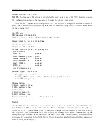
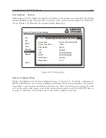
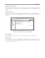
When logging in to the Option 34 using the web interface, the opening screen should be the System
Status information page. This provides an overview of the operation of the Option 34, NTP/PTP
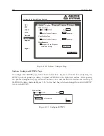
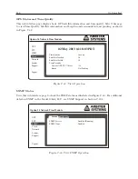
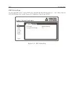
servers. Figure C.23 illustrates the opening System Status page.
Option 34 Network Time Module
Status
Configure
NTP
PTP
SNMP
Clock
Network
Support
Logout
System
Password
Update
Reboot
System Time
System Time Offset
Time Quality
NTP
PTP
SNMP
SNMP Traps
Temperature
01 May 2013 15:01:14 PDT
-158 us
Locked
Running
Enabled (Running)
Enabled (Running)
Enabled
o
33.4 C
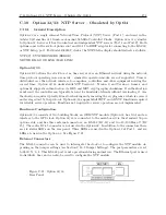
Figure C.23: Startup Page
System Configure Page
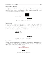
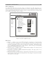
Figure C.24 illustrates the System configuration page for Option 34. It includes configuring for
HTTP or HTTPS (see next section), enabling session time outs for the web interface and console,
responding to ping requests and setting your time zone. Time zone setting only changes the time
as it is read on the clock display. Just as the receiving device must convert the NTP/PTP time as
it arrives at the device to local time zone, so the clock can display local time.
Содержание 1084A
Страница 4: ...iv ...
Страница 6: ...vi ...
Страница 18: ...xviii LIST OF FIGURES ...
Страница 23: ...1 4 Attaching Rack Mount Ears to 1084A B C Series Clocks 3 Figure 1 2 Attaching Rack Mount Ears ...
Страница 24: ...4 Unpacking the Clock ...
Страница 36: ...16 Connecting Inlet Power Input and Output Signals ...
Страница 39: ...4 1 GPS Antenna Installation 19 Figure 4 2 Antenna Mounting Bracket Figure 4 3 Antenna Mounting with AS0044600 ...
Страница 44: ...24 GPS Antenna and Cable Information ...
Страница 114: ...94 Startup and Basic Operation ...
Страница 123: ...B 4 Physical Dimensions 103 Figure B 1 Suggested Mounting of the AS0094500 Surge Arrester ...
Страница 124: ...104 Using Surge Arresters ...
Страница 134: ...114 Options List C 6 2 Option 06 Firmware Setup Figure C 3 Option 06 Firmware Setup ...
Страница 142: ...122 Options List Figure C 5 Option 06 Output Jumper Settings ...
Страница 143: ...C 6 Option 06 Parallel BCD Output 1 millisecond Resolution 123 Figure C 6 Option 06 Board Layout and Jumper Locations ...
Страница 157: ...C 10 Option 17 Parallel BCD Output and Second RS 232C Port 137 Figure C 12 Option 17 Output Jumper Settings ...
Страница 158: ...138 Options List Figure C 13 Option 17 Board Layout and Jumper Locations ...
Страница 163: ...C 13 Option 20A Four Fiber Optic Outputs 143 Figure C 14 Option 20A Jumper Locations ...
Страница 170: ...150 Options List Figure C 16 Option 23 Internal Jumper Setup ...
Страница 172: ...152 Options List Figure C 17 Option 27 Jumper Locations ...
Страница 190: ...170 Options List Figure C 20 Option 29 Connector Signal Locations ...
Страница 246: ...226 Options List ...


