

Model 350S1G6A
30
Rev C
3.4 CONTROL SYSTEM
3.4.1
A60A1, A60A3 Display Assembly, 4.3” LCD (Schematics
10029679, 10030013)
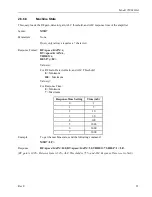
The A60 Control Panel Assembly consists of two 16-bit microcontrollers and about nine other ICs that
monitor and indicate the status of the amplifier. Power is supplied using only a single 5-volt power supply.
The board offers the following:
Feature
Quantity
Open drain outputs
4
Digital outputs
14 (8+6)
Digital inputs (5-volt tolerant)
24
Analog outputs
2
Mixed signal inputs
4
2-channel encoder input
1
Inputs for a keypad
6
Display connectors
1
Serial communication jacks
2
3.4.2
A61 Interface Board (Schematic 10020073)
3.4.3
A66 ALC Board (Schematic 10023927)
This section describes the operation of the level control board. The level control board performs the
following functions:
•
Provides automatic level control of the amplifier’s output when the amplifier is placed in the ALC mode.
•
Limits RF input level to the amplifier when forward or reflected power levels exceed specified levels.
•
Drives forward and reflected indicators on the front panel display.


