Operating manual
Safety Liquid Switch
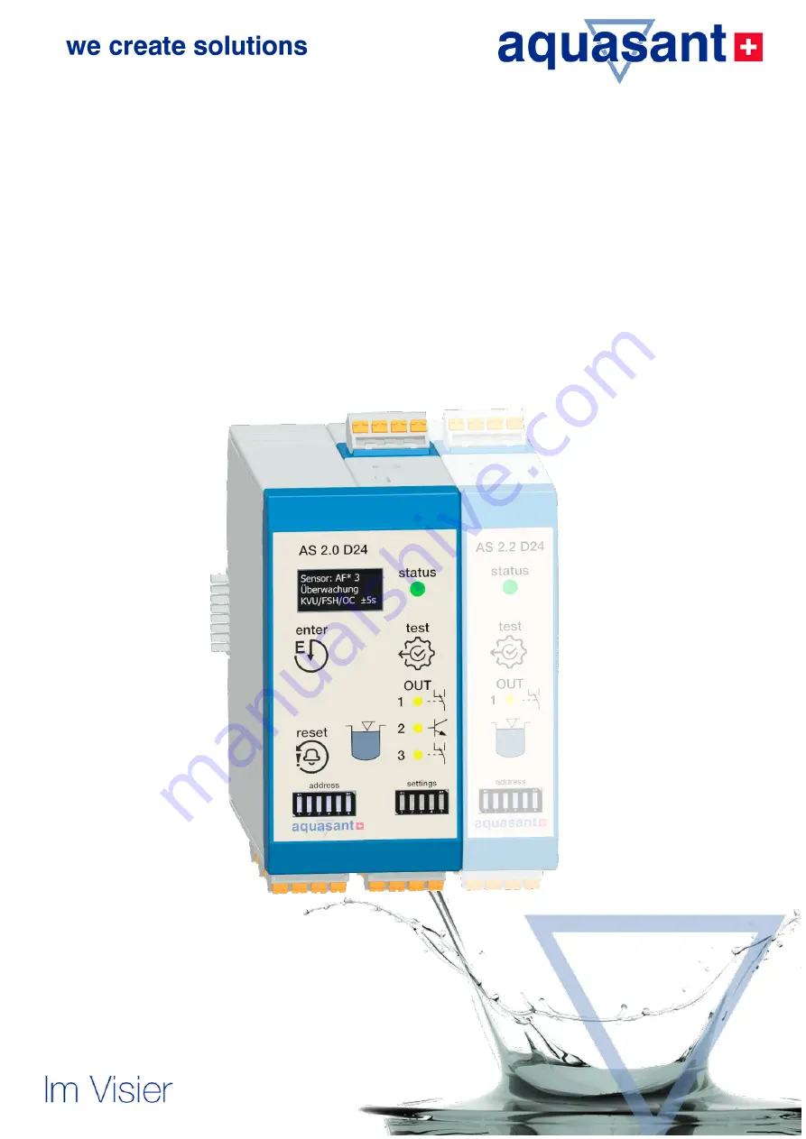
AS 2.0 (2.1) D24 Control Device, 1-channel, SIL2
for connecting electro-optic overfill protection systems, conductivity detectors and Namur sensors
in 2- and 3-wire configurations
Страница 1: ...ing manual Safety Liquid Switch AS 2 0 2 1 D24 Control Device 1 channel SIL2 for connecting electro optic overfill protection systems conductivity detectors and Namur sensors in 2 and 3 wire configura...
Страница 2: ...AS 2 0 D24 2 Change index Version Date Description 1 00 04 2021 First version for firmware 1 00...
Страница 3: ...EB Device_AS20D24G Manual docx Version 210422 1 Firmware AS 2 0 D24 V1 00 Pages 40 Changes Subject to change without notice 2021 Aquasant Messtechnik AG claims copyright protection for this document T...
Страница 4: ...al functions 11 3 3 Applications 11 4 Installation 14 4 1 Conditions for assembly 14 4 2 Control device assembly on DIN rail 14 4 3 Electrical connections 16 5 Operation and parametrisation 19 5 1 Des...
Страница 5: ...ensions top view side view 15 Figure 9 Connection diagram for the AS2 0 D24 G 18 Figure 10 Nameplate for the AS 2 0 D24 20 Figure 11 DIN rail disassembly 33 Table 1 Sensor selector switch 21 Table 2 6...
Страница 6: ...manual is intended for trained specialists The contents of this manual must be made accessible to each specialist and must be applied 1 2 Symbols A yellow triangle indicates a warning Each warning sig...
Страница 7: ...st certificate EMC certificate of conformity QA documentation Swiss Association for Technical Inspections SVTI test report equipment for water polluting liquids 1 3 2 Device specific additional docume...
Страница 8: ...ised by the plant operator Familiar with national regulations Instructions in the manual and additional documentation have been read and understood Follow instructions and conditions 2 3 Intended use...
Страница 9: ...y of Equipment NE 53 Compatibility of field devices and display adjustment components For more information go to www namur de 2 5 Functional approvals 2 5 1 Switzerland Swiss Association for Technical...
Страница 10: ...AS2 0 basic module is monitored up to the sensor in accordance with the Namur EN107 standard For the 3 wire electro optical systems the current sensor reading is monitored and provides early warning o...
Страница 11: ...tion the signal is received from the road tanker and enabled as a relay contact This means that the enable signal can be transmitted to the PLC or directly to the slider so that it is closed This ensu...
Страница 12: ...et 4 3 HL alarm NPN OC acknowledgment HL alarm delayed delay Fault message redundant Relay 3 Relay 1 1 Relay 1 2 OC 2 Relay 4 Relay de energized in alarm condition AF overfill protection Figure 2 Usin...
Страница 13: ...Relay 4 Figure 4 Using leakage monitoring schematic 3 3 4 Oil detection monitoring Possible applications Monitoring rainwater in a basin for heavy or light oil leaks Storage tank LS21 1 surface oil d...
Страница 14: ...to IEC EN 60664 1 Observe the installation instructions according to IEC EN 60079 14 The device may only be installed and operated if the device is installed in an enclosure that meets the requiremen...
Страница 15: ...bus connector should be used The T bus is snapped into the DIN rail and is pushed in and connected with further connectors The T bus connector stays in the DIN rail when the device is removed Place t...
Страница 16: ...possible use power cables with an upstream residual current circuit breaker RCCB rated tripping current max 30 mA The connection values for the power supply must be observed as stated in the technica...
Страница 17: ...marking on the device may be routed into the potentially explosive area observe the zones The intrinsically safe circuits must be installed in accordance with the applicable erection regulations and w...
Страница 18: ...ledgment HL alarm Acknowledgment impulse 24VDC Collective alarm fault 24VDC Power supply 24VDC HL alarm OC delayed output Relay 1 1 HL Alarm output Relay 3 HL alarm output can be acknowledged for horn...
Страница 19: ...or terminals Relay 3 output 6 Grey push in connector terminals OC relay 4 output 7 Device status and power indicator RGB LED 8 Test button 9 Liquid level alarm relay yellow LED 10 OC output time delay...
Страница 20: ...ry of the AS2 x control device consists of Control device type AS 2 x D24 for DIN rail mounting x7 connectors AS2 0 coded Quick guide and Ex documentation optional printed The following are accessorie...
Страница 21: ...oil detection Namur sensors The display shows the parametrised sensor Standard parametrisation when purchasing the device without sensor AF liquid sensor with 3 wire connection As delivered parametri...
Страница 22: ...g cable a 120 terminating resistor must be set across terminals A B at the first and last nodes of the bus from firmware version 1 10 and above If the bus is used or if AS2 2 devices have to communica...
Страница 23: ...to red LED Enter Saves a value in the parametrisation increments a parameter Reset Acknowledges relay K3 in event of HL alarm Acknowledges a fault on the display Table 5 Description of button functio...
Страница 24: ...ay with power on Vertical scrolling text After 4 seconds the display continues to next screen Operating display SENS AF S FH Q H Operating display Monitoring active F105 AF sensor critical After ackno...
Страница 25: ...ling Delay time 1 0s Define the time delay 3 Maintenance Not used in this FW1 0 Inactive Year 1 Year 2 Year 3 Reset Time interval for the KVU plant inspection Scrolling display Display K3 4 Alarm reac...
Страница 26: ...CK S N 200001 FW 1 0 Sensor type with current and average sensor reading Displays the device status Control device serial no firmware version Press the test button SENS LS mv low SYS CHECK S N 20001 F...
Страница 27: ...ting range 0 0 5 1 60 seconds loop with increments in 1s steps Inactive Year 1 Year 2 Not used in this FW 1 0 version 2 Maintenance service according Selection Inactive 1 year 2 years 3 years reset Ad...
Страница 28: ...ged or as a controller with two further sensor modules 2 Internal alarm buzzer On The internal alarm buzzer can be activated deactivated 3 Error reactivation x week s If a fault is displayed and is on...
Страница 29: ...r liquid sensor is clean dry and is not exposed to daylight that if several modules are connected to each other the bus DIL switch for addressing the devices is set and the terminating resistor has be...
Страница 30: ...own on the display If the button is pressed longer 5s the relays drop out the status LED changes to red and the yellow LEDs light up The sensor or detector readings are checked with a tester and addit...
Страница 31: ...alarm relay 1 2 3 F100 F101 No sensor Sensor is not connected Red OFF No OFF F102 Wire break Connection cable to the sensor is interrupted Red OFF No OFF F103 Sensor incorrectly assigned Connected se...
Страница 32: ...ertain time Report this for the next maintenance F106 Com Time out Restart the device power cut or menu 6 initialization Attention parameters have to be set again F107 Excessive temperature Make sure...
Страница 33: ...ail Figure 11 DIN rail disassembly 6 5 2 Disposal under WEEE Directive The Waste Electrical and Electronic Equipment WEEE Directive which came into force on 13 February 2003 has brought about a major...
Страница 34: ...zzer Acoustic sensor alarm resettable Status configuration Button Name Function Test button Device test function Name Function Input button Button to confirm input Name Function Reset button Button to...
Страница 35: ...een Cable type Cable resistance Min 3x0 75 mm2 Max 300 Rotary switch Position 5 Fault monitoring Sensor misconfiguration Connection error Cable break Sensor reading Fail safe Yes AF with VE9 Connectio...
Страница 36: ...oltage V DC Input voltage 8 5 operating voltage V DC high logic 0 3 V DC low logic Output current 22 mA 12 V DC operating voltage 54 mA 28 V DC operating voltage Internal resistance Output resistance...
Страница 37: ...tion class Intrinsically safe Um 28 8 VDC U0 A C 7 2 V B C 7 2 V D C 10 2 V I0 A C 13 3 mA B C 41 8 mA D C 13 3 mA P0 linear characteristic A C 23 8 mW B C 75 3 mW D C 33 8 mW Ci Li A B C D 0 F 0 nH C...
Страница 38: ...AS 2 0 D24 38 7 2 Commissioning test report...
Страница 39: ...Aquasant Messtechnik AG 39 7 3 Declaration of conformity...
Страница 40: ...AS 2 0 D24 40 Aquasant Messtechnik AG Hauptstrasse 22 CH 4416 Bubendorf Switzerland T 41 61 9355000 info aquasant mt com www aquasant com...