Page | 1
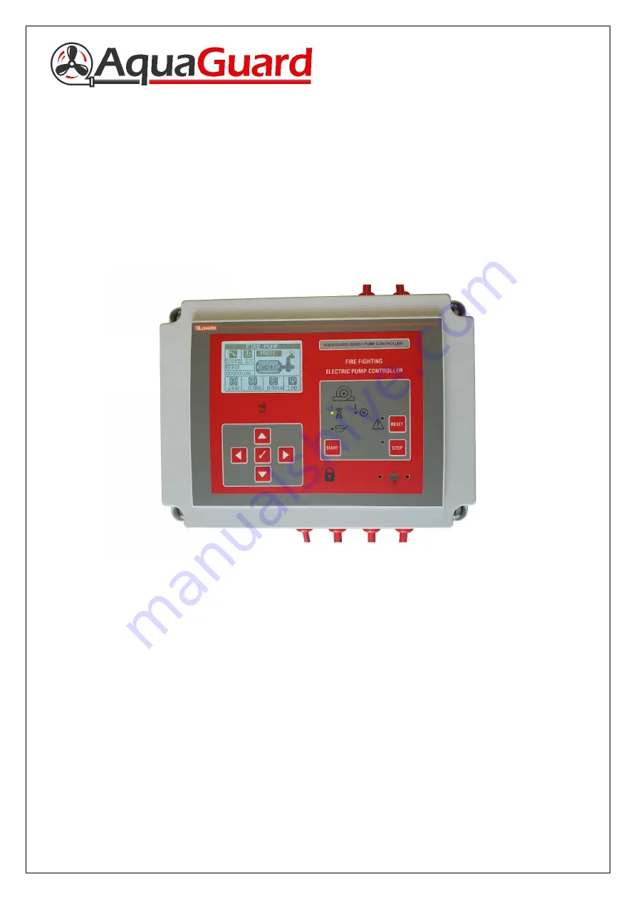
AquaGuard BS9251:2021 Fire Pump Controller
User & Installation Manual
Страница 1: ...Page 1 AquaGuard BS9251 2021 Fire Pump Controller User Installation Manual...
Страница 2: ...allation Guide Page 5 4 Controller Set Up and User Guide Page 6 8 5 Commissioning Page 9 6 Annual Maintenance Page 10 7 Fault Alarm Table Page 11 8 Troubleshooting Page 12 13 If additional assistance...
Страница 3: ...ly limit Fire Mode If pressure loss and flow are detected by either of the two pressure switches and the flow switch then pump will operate in fire mode until manually shut down Test Mode Each Monday...
Страница 4: ...Page 4 2 User Interface 2 1 AquaGuard fire pump controller button and LED description 2 2 AquaGuard fire pump controller LCD Display Home Screen description Controller Home Screen...
Страница 5: ...be wired to a suitable isolator fed directly from the electrical distribution board protected by a dedicated RCD RCBO suitably sized for the fire pump installed Installation 3 4 If purchasing in kit f...
Страница 6: ...ll volume in the pump manifold Warning Tank must be full pump must be fully primed from all bleed nipples and all suction valves must be open prior to powering the controller up for the first time 4 2...
Страница 7: ...con enter the user password 2000 press right to the key symbol then press ok tick Note Access to the setup menu is possible by entering an advanced password but the installer will be required to speak...
Страница 8: ...ult whereby the pump was running when not called upon then a fault signal is transmitted Note This fault will be present when operating the pump set in Fire Mode for more than one minute this will res...
Страница 9: ...hat the pressure switches are set within 0 3 bar of each other Refer to pressure switch instruction manual for setting instructions this should be undertaken with the Aquaguard pump controller switche...
Страница 10: ...ion 4 4 enter main menu navigate to the Enter password section enter code 2000 then press ok on the key symbol 3 Enter main menu navigate to the Commands menu while holding the Manual mode button pres...
Страница 11: ...Page 11 8 Fault Alarm Table If any faults are present on the controller then these will be displayed on the LCD display with a code A01 A38 or UA1 8 see alarm table below for description...
Страница 12: ...ssure low or at zero Pressure switches not wired correctly or pressure switch setting too low Pressure switch cable wired to flow switch Wire pressure switches between COM and 1 normally closed Set co...
Страница 13: ...e if necessary Fault present on pump controller Refer to fault alarm table in section 8 to identify fault and possible action required Undertake action if possible Call Aquaguard if problem persists P...