


8
Cousteau/ SEA First Stage Service & Repair Manual
© 2000 Aqua Lung America, Inc.
Reassembly Procedures
NOTE: Before performing any reassembly, it is important to
inspect all parts, both new and those that are being reused,
to ensure that every part and component is perfectly clean
and free of any dust, corrosion, or blemishes. Before dress-
ing each O-ring with Christo-Lube®, check to ensure it is
clean, supple, and free of any blemish.
WARNING: Use only genuine Aqua Lung parts, subassem-
blies, and components whenever assembling any Aqua Lung
product. DO NOT attempt to substitute an Aqua Lung part
with another manufacturer’s, regardless of any similarity in
shape, size, or appearance. Doing so may render the prod-
uct unsafe, and could result in serious injury or death.
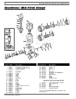
1.
Install the O-ring(12) onto the crown(11), and place the crown
over the pin of the extractor tool (P/N 1094-36) with the
orifice sealing surface facing up.
2.
While holding the first stage body(10) vertical with the high
pressure side facing straight up, insert the handle of the
extractor tool into the body. Pass the tool through the low
pressure side so that the crown remains inside, resting above
its seating shoulder (see Fig. 4).
3.
Insert the handle of the extractor tool into the high pressure
side of the body once again, and press the crown into place so
that it fits snugly over the seating shoulder.
4.
Turn the body over and stand it on a padded surface with the
high pressure side facing down. Place the small end of the
pin support(25) inside the opening in the center of the body.
5.
Lay the diaphragm(26a) inside the body, and gently tamp it
down below the threads until it is seated evenly on all sides.
6.
Lay the thrust washer(26b) inside the body, and tamp it down
below the threads until it is evenly seated over the diaphragm.
7.
Lay the spring pad(27) in the center of the diaphragm with the
mating tab facing up, and thread the spring retainer(28 or 32)
clockwise into the body by hand until snug.
8.
Install a vise mounting tool (P/N 1003-95), or a discharged
C0
2
cartridge (P/N 7039-09) connected to a HP port adapter
(P/N 1020-85), into the HP port of the first stage body.
WARNING: DO NOT use a C0
2
cartridge which has not
been discharged. Doing so may cause the cartridge to
rupture, resulting in serious personal injury.
9.
Secure the vise mounting tool in a vise so the first stage
stands vertical with the spring retainer facing up. Apply a
torque wrench with 30mm crow-foot, or use a 34mm crow
foot for the “D” environmental version spring retainer, and
Fig. 4


