Aqua Flo GEN5-8R12 Скачать руководство пользователя страница 9

9 |

P a g e

Installation 

Step 1:

   Once both the orientation and location have been selected, securely fasten the rack to 

a suitable backing. As the rack system is extremely heavy when filled with water, it is imperative 

that the rack be mounted with suitable fasteners for the particular installation.. Mounting to a 

drywall backing is not suitable, unless the rack is fastened directly to the wall studs.
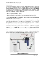
Step 2:

  The use of a by-pass assembly is recommended as it will allow you to isolate the UV 

system This will allow for easier access in case maintenance is required.

Step 3: 

For water supplies where the maximum flow rate is unknown, a flow restrictor is rec-

ommended so that the rated flow of your particular AQUA FLO system is not exceeded. The flow 

restrictor should be installed on the inlet port of the reactor.

Step 4:

   It is recommended to have a licensed plumber connect the UV reactor to the water 

supply and may be a requirement depending on where you are located.

Step 5: 

Connect both the inlet and outlet to the rack system with the applicable connections 

based on your particular plumbing requirements. The inlet port of the filters is a 1” FNPT connec-

tion and the outlet port of the UV reactor is a 1” MNPT connection.
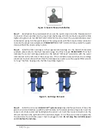
Step 6:

  Once the system has been plumbed in, gently remove the quartz sleeve from its pack-

aging being careful not to touch the length with your hands. The use of cotton gloves is recom-

mended for this procedure as oils from the hands can leave residue on the sleeve and lamp 

which can ultimately block the UV light from getting to the water.

Carefully slide the sleeve into the reactor until you can feel it hit the opposite end of the reactor. 

Align the sleeve so it centered along the length of the reactor, then gently push it in to lock it into 

the internal centering springs in the far side of the reactor. 
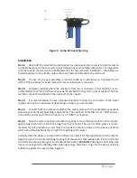
CAUTION:

 Pushing too hard when the 

sleeve is not aligned can damage the centering springs. Slide the o-ring onto the sleeve until it is 

butted up against the reactor (See Figure 4).

Figure 3. Lamp Removal Spacing

Содержание GEN5-8R12

Страница 1: ...R S MANUAL Operation Installation Instructions AQUA FLO Rack Mount Systems System Rated Flow Sediment Carbon GEN5 8R1 8 gpm YES NO GEN5 8R12 8 gpm YES YES GENH5 8R1 15 gpm YES NO GENH5 8R12 15 gpm YES...

Страница 2: ...pply with a UV system gives you reassurance that your family will have access to safe drinking water throughout your entire home with no chance of microbiological contamination This is chemical free p...

Страница 3: ...e UV Sensor 14 Temperature Management Devices 14 Operation 15 Controller 15 Power up Sequence 15 AQUA FLO Operational Screens 16 AQUA FLO6 0 Operational Screens 17 AQUA FLO6 0 UV Intensity 17 Lamp Cou...

Страница 4: ...ervice instructions if required 7 Do not use this system for any purpose other than what it was intended for Misuse of this system could potentially cause harm to the user or others 8 Your system is i...

Страница 5: ...required will depend on parameters being treated Hardness 7 gpg 120 mg L if hardness level is 7 gpg or slightly below the quartz sleeve must be cleaned periodically in order to ensure effi cient UV p...

Страница 6: ...6 P a g e Assembly Unpack the system and ensure all the components are included with the system Your system is shipped with the following components...

Страница 7: ...pump starts 3 Close the faucet and using a second hand watch record the length of time in seconds until the pump stops This is known as the cycle time 4 Then using a container of known volume prefera...

Страница 8: ...ng plate 4 screws for a single filter model and 8 screws for a double filter model Step 3 Carefully lower the filter head or heads from the rack assembly and rotate 180 de grees Reassemble onto the ra...

Страница 9: ...requirement depending on where you are located Step 5 Connect both the inlet and outlet to the rack system with the applicable connections based on your particular plumbing requirements The inlet port...

Страница 10: ...ates the correct cartridge position for the default left hand orientation with the water inlet located on the left side of the rack system If the orientation was switched the cartridge placement must...

Страница 11: ...illing up with water it is a good idea to physically depress the red pressure relief button located on the top of the filter head Simply depress the button down venting the air until water appears at...

Страница 12: ...ding Figure 10 Ground Screw Connection Step 14 Your system is now ready to be plugged into the appropriate GFCI protected outlet Refer to the following section before any water is allowed to flow thro...

Страница 13: ...eaning At a minimum the quartz sleeve should be cleaned on an annual basis The following steps outline a basic clean ing procedure Step 1 If a by pass assembly is installed shut the inlet valve off to...

Страница 14: ...y out of the sensor port Step 6 Holding the sensor in your hand wipe the flat portion sensor face of the sensor with isopropyl alcohol using a clean lint free cloth Step 7 Replace sensor following ste...

Страница 15: ...providing any applicable fault messages and system diagnostics The controllers used in both the monitored and non monitored systems are identical All controllers include an infinite ex pandability po...

Страница 16: ...Finally a final start up complete screen is displayed The system will now be ready to disinfect water flow all detected modules lamp reaching max output successful start up AQUA FLO Operational Scree...

Страница 17: ...y the sensor UV intensity can be affected by poor water quality scaling on the quartz sleeve and or sensor lamp failure or lamp expiring The following screens show the UV Intensity dropping Below 56 t...

Страница 18: ...eriod of five seconds after which the screen below will be displayed After the seven days deferral expires the alarm will sound once again The deferral can be repeated as many times as you wish PLEASE...

Страница 19: ...human consumption during this period the water must be boiled minimum 20 minutes at a full boil prior to consumption QR Codes A QR code Quick Response code is a matrix barcode first designed for the...

Страница 20: ...tacts In normal operation the OK and COM contacts will be connected and in a fault condition Low UV Lamp fail Power Fail the Fault and COM contacts will be connected Maximum Contact Rat ing is 1A 120V...

Страница 21: ...45 high output lamp Power Watts 23 21 230V 57 48 230V Replacement Lamp 40040096 40040020 Replacement Sleeve 40040042 Reactor Dimensions 8 9 x 50 8 cm 3 5 x 20 Chamber Material Polished 316L Stainless...

Страница 22: ...t be liable for any costs of removal installation transportation or any other charges which may arise in connection with a warranty claim Products which are sold but not manufactured by AQUA FLO are s...

Страница 23: ...AW ANY AND ALL EXPRESS OR IMPLIED WARRANTIES NOT SET FORTH HEREIN ARE WAIVED AND DISCLAIMED INCLUDING ANY IMPLIED WARRANTY OF MERCHANTABILITY OR FITNESS FOR A PARTICULAR USE CANATURE S LIABILITY UNDER...

Страница 24: ...Canature Watergroup Inc 655 Park St 9760 Mayflower Park Drive Regina SK S4N 5N1 Suite 110 CANADA Carmel IN 46032 USA Toll Free 877 444 3348 Toll Free 877 771 6789 PN 910195...

Отзывы: