3
- 7
MOTOR
ENGINE
3.1.1 DESMONTAJE TUBOS DE ESCAPE
Lea con cuidado 1.4 (PRECAUCIONES E INFORMA-
CIONES GENERALES).
Deje enfriar el motor hasta que el mismo al-
cance la temperatura ambiente.
◆
D e s m o n t e e l p a n e l l a t e r a l d e r e c h o , v é a s e
7.1.4 (DESMONTAJE PANELES LATERALES DE-
RECHO E IZQUIERDO).
◆
Saque el radiador, véase 5.2 (DESMONTAJE RADIA-
DOR).
◆
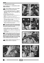
Destornille y quite los dos tornillos (1-2).
◆
Desmonte el soporte radiador (3).
◆
Destornille y quite los dos tornillos (4-5) guardando las
arandelas.
◆
Desmonte el elemento de protección (6).
◆
Destornille dando pocas vueltas a los dos tornillos (7-
8) sobre las abrazaderas (9-10).
◆
Destornille y quite las dos tuercas (11) que sujetan la
brida del tubo de escape al cilindro.
Par de apriete tuercas (11): 25 Nm (2,5 kgm)
◆
Desplace hacia adelante el grupo tubos de escape
(12) lo suficiente para extraerlos de sus sedes sobre el
cilindro.
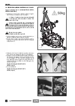
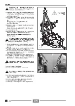
Para que la extracción del grupo tubos de es-
cape (12) resulte más fácil, golpee moderada-
mente (utilizando un martillo de goma) sobre uno de
los dos soportes elemento de protección (véase figu-
ra).
◆
Destornille dando pocas vueltas al tornillo (13) sobre
la abrazadera (14).
◆
Extraiga el tubo (15) del grupo tubos de escape (12).
◆
Si ljunta de grafito (16) resulta desgastado, sustitúya-
lo.
◆
Desmonte el grupo tubos de escape (12) extrayéndolo
desde la parte delantera.
Desplace el grupo tubos de escape (12) con
pequeños movimientos, buscando la combi-
nación mejor para su extracción (levante la parte de-
lantera, baje la parte trasera de manera que todo rea-
lice un movimiento de enrosque hacia adelante; la
parte inferior trasera ha de pasar entre las dos espi-
ras del muelle amortiguador trasero) (véase figura).
Tape las aberturas de escape del motor, impi-
diendo la entrada de cuerpos extraños.
a
c
c
a
3.1.1 REMOVING THE EXHAUST PIPES
Read 1.4 (PRECAUTIONS AND GENERAL INFORMA-
TION) carefully.
Let the engine cool down until it reaches room
temperature.
◆
Remove the right side, see 7.1.4 (REMOVING THE
RIGHT AND LEFT SIDES).
◆
Remove the radiator, see 5.2 (REMOVING THE RA-
DIATOR).
◆
Unscrew and remove the two screws (1-2).
◆
Remove the radiator support (3).
◆
Unscrew and remove the two screws (4-5), taking the
washers.
◆
Remove the guard (6).
◆
Loosen the two screws (7-8) on the clamps (9-10).
◆
Unscrew and remove the two nuts (11) that fasten the
exhaust pipe flange to the cylinder.
Nut (11) driving torque: 25 Nm (2.5 kgm).
◆
Move the exhaust pipe unit (12) forward as much as
necessary to withdraw them from the seats on the cyl-
inder.
To facilitate the withdrawing of the exhaust
pipe unit (12), strike slightly (by means of a
rubber hammer) one of the two supports of the guard
(see figure).
◆
Loosen the screw (13) on the clamp (14).
◆
Withdraw the pipe (15) from the exhaust pipe unit (12).
◆
If the graphite sealing ring (16) is broken or worn,
change it.
◆
Remove the exhaust pipe unit (12) by withdrawing it
from the front part.
Shift the exhaust pipe unit (12) with small
movements, trying to find the right position to
withdraw it (lift the front part, lower the rear part giv-
ing the whole unit a forward screwing movement; the
rear lower part must pass through the turns of the
rear shock absorber spring) (see figure).
Plug the engine exhaust openings, in order to
avoid any accidental introduction of foreign
matters.
a
c
c
a
Содержание Pegaso 650
Страница 1: ......
Страница 3: ...0 4 NOTE NOTES ANMERKUNGEN ...
Страница 4: ...1 1 1 2 3 4 5 6 7 8 INFORMAZIONI GENERALI INFORMACIONES GENERALES GENERAL INFORMATION ...
Страница 42: ......
Страница 69: ...3 1 1 2 3 4 5 6 7 8 MOTORE MOTOR ENGINE ...
Страница 90: ...3 22 MOTORE NOTE NOTAS NOTES ...
Страница 91: ...4 1 1 2 3 4 5 SISTEMA DI ALIMENTAZIONE SISTEMA DE ALIMENTACIÓN FUEL SYSTEM ...
Страница 116: ...4 26 SISTEMA DI ALIMENTAZIONE NOTE NOTAS NOTES ...
Страница 117: ...5 1 1 2 3 4 5 6 7 8 IMPIANTO DI RAFFREDDAMENTO SISTEMA DE REFRIGERACIÓN COOLING SYSTEM ...
Страница 130: ...5 14 IMPIANTO DI RAFFREDDAMENTO SISTEMA DE REFRIGERACIÓN COOLING SYSTEM NOTE NOTAS NOTES ...
Страница 131: ...6 1 6 1 2 3 4 5 6 7 8 IMPIANTO ELETTRICO INSTALACIÓN ELÉCTRICA ELECTRICAL SYSTEM ...
Страница 176: ...IMPIANTO ELETTRICO INSTALACIÓN ELÉCTRICA ELECTRICAL SYSTEM 6 46 NOTE NOTAS NOTES ...
Страница 177: ...7 1 1 2 3 4 5 6 7 8 CICLISTICA PARTE CICLO CHASSIS PARTS ...
Страница 226: ... 67 3 57 2 66 6 3 576 7 50 5827 3267 5 25 58 75 6 5 5 5 ...
Страница 242: ... 67 3 57 2 66 6 3 576 7 66 5 12 17 5 25 5 12 17 52 5217 5 ...
Страница 246: ... 67 3 57 2 66 6 3 576 7 70 5 12 3267 5 25 5 12 75 6 52 5 5 5 ...
Страница 272: ... 67 3 57 2 66 6 3 576 7 96 NOTE NOTAS NOTES ...
Страница 273: ...8 1 1 2 3 4 5 6 7 8 INFORMAZIONI PER LE RIPARAZIONI INFORMACIONES PARA LAS REPARACIONES REPAIRS ...
Страница 301: ...INFORMAZIONI PER LE RIPARAZIONI INFORMACIONES PARA LAS REPARACIONES REPAIRS 8 29 E F E F G H G H ...
Страница 302: ...INFORMAZIONI PER LE RIPARAZIONI INFORMACIONES PARA LAS REPARACIONES REPAIRS 8 30 I L I M L N M N ...
Страница 303: ...INFORMAZIONI PER LE RIPARAZIONI INFORMACIONES PARA LAS REPARACIONES REPAIRS 8 31 O P Q P O R Q R ...
Страница 310: ...INFORMAZIONI PER LE RIPARAZIONI INFORMACIONES PARA LAS REPARACIONES REPAIRS 8 38 NOTE NOTAS NOTES ...
Страница 311: ...INFORMAZIONI PER LE RIPARAZIONI INFORMACIONES PARA LAS REPARACIONES REPAIRS 8 39 ...


