7
- 55
3$57(&,&/2
&+$66,63$576
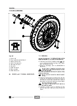
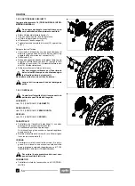
7.3.2 SUSTITUCION COJINETES
Lea con mucho cuidado 1.4 (PRECAUCIONES E IN-
FORMACIONES GENERALES).
Después de cada desmontaje controle los co-
jinetes y, si es necesario, sustitúyalos.
X
Extraiga el distanciador lateral derecho (7).
X
Con un trapo limpie los dos lados del cubo.
X
+
Quite la junta estanca (8).
X
+
Quite la arandela Seeger (9).
X
Quite la corona con el cubo (10) y la junta amortigua-
dora (11).
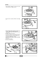
Empuje hacia afuera, en el siguiente orden:
X
El cojinete (12), golpeando sobre una herramienta
adecuada (que tenga un diámetro igual al anillo inte-
rior de los cojinetes) apoyada contra el anillo interior
del cojinete (16).
X
El cojinete (14).
X
Del lado contrario, golpeando sobre la misma herra-
mienta apoyada contra el distanciador central (13),
empuje hacia afuera el cojinete (16) y el distanciador
lateral izquierdo (15) y luego el distanciador mismo.
X
Limpie muy bien el interior del cubo.
Para montar nuevamente los cojinetes, utilice
una herramienta con diámetro igual al anillo
exterior de los cojinetes.
No golpee sobre las bolas y/o sobre el anillo interior.
Lave todos los componentes con detergente
limpio.
7.3.3 CONTROL
Controle la integridad de todos los compo-
nentes y, especialmente, de los indicados a
continuación.
COJINETES
Véase 7.2.3 (CONTROL; COJINETES).
EJE DE LA RUEDA
Véase 7.2.3 (CONTROL; EJE DE LA RUEDA).
LLANTA
Véase 7.2.3 (CONTROL; LLANTA).
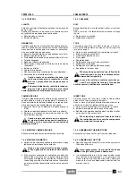
AMORTIGUADOR DE TRACCIÓN
X
Controle que no estén dañados o desgastados los
sectores de la amortiguador de tracción (1). Si es ne-
cesario, sustituya la amortiguador de tracción. Hay
que sustituir la amortiguador de tracción en caso de
juego excesivo.
X
Gire manualmente la corona (2) y controle el juego en-
tre corona y cubo de la rueda (3).
CORONA
X
Controle las condiciones de los dientes de la corona
(2) y del piñón. Si están muy desgastados, sustituya
corona, piñón y cadena de transmisión, véase 7.1.23
(DESMONTAJE CADENA DE TRANSMISION).
Para evitar que los componentes nuevos se
desgasten prematuramente, sustitúyalos en
conjunto.
NEUMATICO
X
Controle el estado del neumático, véase 2.23 (NEU-
MÁTICOS).
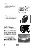
7.3.2 CHANGING THE BEARINGS
Read 1.4 (PRECAUTIONS AND GENERAL INFORMA-
TION) carefully.
The bearings must be checked and if neces-
sary changed every time they are disassem-
bled.
X
Remove the right side spacer (7).
X
Clean both sides of hub with a cloth.
X
+
Remove the seal (8).
X
+
Remove the snap ring (9).
X
Remove the crown gear complete with hub (10) and
flexible coupling (11).
Push out, in this order:
X
The bearing (12), by hitting against a suitable punch
(with diameter equal to the inner ring of the bearings)
resting on the inner ring of the bearing (16).
X
The bearing (14).
X
On the opposite side, hitting against the same punch
resting on the central spacer (13), push out the bear-
ing (16), the left side spacer (15) and the spacer itself.
X
Thoroughly clean the inside of the hub.
Upon reassembly, to insert the bearings use a
punch with diameter equal to the outer ring of
the bearings.
Do not strike against the balls and/or the inner ring.
Wash all the components with a clean deter-
gent.
7.3.3 CHECKING
Make sure that all the components are sound,
particularly the following:
BEARINGS
See 7.2.3 (CHECKING; BEARINGS).
WHEEL PIN
See 7.2.3 (CHECKING; WHEEL PIN).
RIM
See 7.2.3 (CHECKING; RIM)
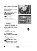
FLEXIBLE COUPLING
X
Check that the small blocks on the flexible coupling (1)
are not damaged and/or excessively worn.
If necessary, change the flexible coupling. If excessive
clearence is noticed, the coupling must be changed.
X
Manually rotate the crown gear (2) and check the
clearence between crown gear and wheel hub (3).
CROWN GEAR
X
Check the conditions of the crown gear teeth (2) and of
the pinion. If you notice excessive wear, change the
crown gear, the pinion and the gearing chain, see
7.1.23 (REMOVING THE GEARING CHAIN).
To avoid premature wear of the new compo-
nents, change them all.
TYRE
X
Check the conditions of the tyre, see 2.23 (TYRES).
Содержание Pegaso 650
Страница 1: ......
Страница 3: ...0 4 NOTE NOTES ANMERKUNGEN ...
Страница 4: ...1 1 1 2 3 4 5 6 7 8 INFORMAZIONI GENERALI INFORMACIONES GENERALES GENERAL INFORMATION ...
Страница 42: ......
Страница 69: ...3 1 1 2 3 4 5 6 7 8 MOTORE MOTOR ENGINE ...
Страница 90: ...3 22 MOTORE NOTE NOTAS NOTES ...
Страница 91: ...4 1 1 2 3 4 5 SISTEMA DI ALIMENTAZIONE SISTEMA DE ALIMENTACIÓN FUEL SYSTEM ...
Страница 116: ...4 26 SISTEMA DI ALIMENTAZIONE NOTE NOTAS NOTES ...
Страница 117: ...5 1 1 2 3 4 5 6 7 8 IMPIANTO DI RAFFREDDAMENTO SISTEMA DE REFRIGERACIÓN COOLING SYSTEM ...
Страница 130: ...5 14 IMPIANTO DI RAFFREDDAMENTO SISTEMA DE REFRIGERACIÓN COOLING SYSTEM NOTE NOTAS NOTES ...
Страница 131: ...6 1 6 1 2 3 4 5 6 7 8 IMPIANTO ELETTRICO INSTALACIÓN ELÉCTRICA ELECTRICAL SYSTEM ...
Страница 176: ...IMPIANTO ELETTRICO INSTALACIÓN ELÉCTRICA ELECTRICAL SYSTEM 6 46 NOTE NOTAS NOTES ...
Страница 177: ...7 1 1 2 3 4 5 6 7 8 CICLISTICA PARTE CICLO CHASSIS PARTS ...
Страница 226: ... 67 3 57 2 66 6 3 576 7 50 5827 3267 5 25 58 75 6 5 5 5 ...
Страница 242: ... 67 3 57 2 66 6 3 576 7 66 5 12 17 5 25 5 12 17 52 5217 5 ...
Страница 246: ... 67 3 57 2 66 6 3 576 7 70 5 12 3267 5 25 5 12 75 6 52 5 5 5 ...
Страница 272: ... 67 3 57 2 66 6 3 576 7 96 NOTE NOTAS NOTES ...
Страница 273: ...8 1 1 2 3 4 5 6 7 8 INFORMAZIONI PER LE RIPARAZIONI INFORMACIONES PARA LAS REPARACIONES REPAIRS ...
Страница 301: ...INFORMAZIONI PER LE RIPARAZIONI INFORMACIONES PARA LAS REPARACIONES REPAIRS 8 29 E F E F G H G H ...
Страница 302: ...INFORMAZIONI PER LE RIPARAZIONI INFORMACIONES PARA LAS REPARACIONES REPAIRS 8 30 I L I M L N M N ...
Страница 303: ...INFORMAZIONI PER LE RIPARAZIONI INFORMACIONES PARA LAS REPARACIONES REPAIRS 8 31 O P Q P O R Q R ...
Страница 310: ...INFORMAZIONI PER LE RIPARAZIONI INFORMACIONES PARA LAS REPARACIONES REPAIRS 8 38 NOTE NOTAS NOTES ...
Страница 311: ...INFORMAZIONI PER LE RIPARAZIONI INFORMACIONES PARA LAS REPARACIONES REPAIRS 8 39 ...


