2–21
PacketMax 5000 Installation and Operation Manual, 10007678 Rev J
Chapter 2. Base Station Components
2.
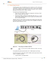
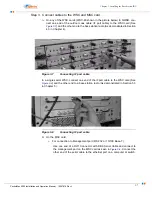
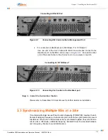
Connect the serial DB9 end to the PC. This connection will assist in aligning
the antenna and issuing CLI commands.
2.11.1 Serial Connection Instructions
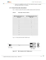
shows the pinout of the serial connection needed to build a serial cable.
Table 2-I
Serial Cable Connector Pinouts
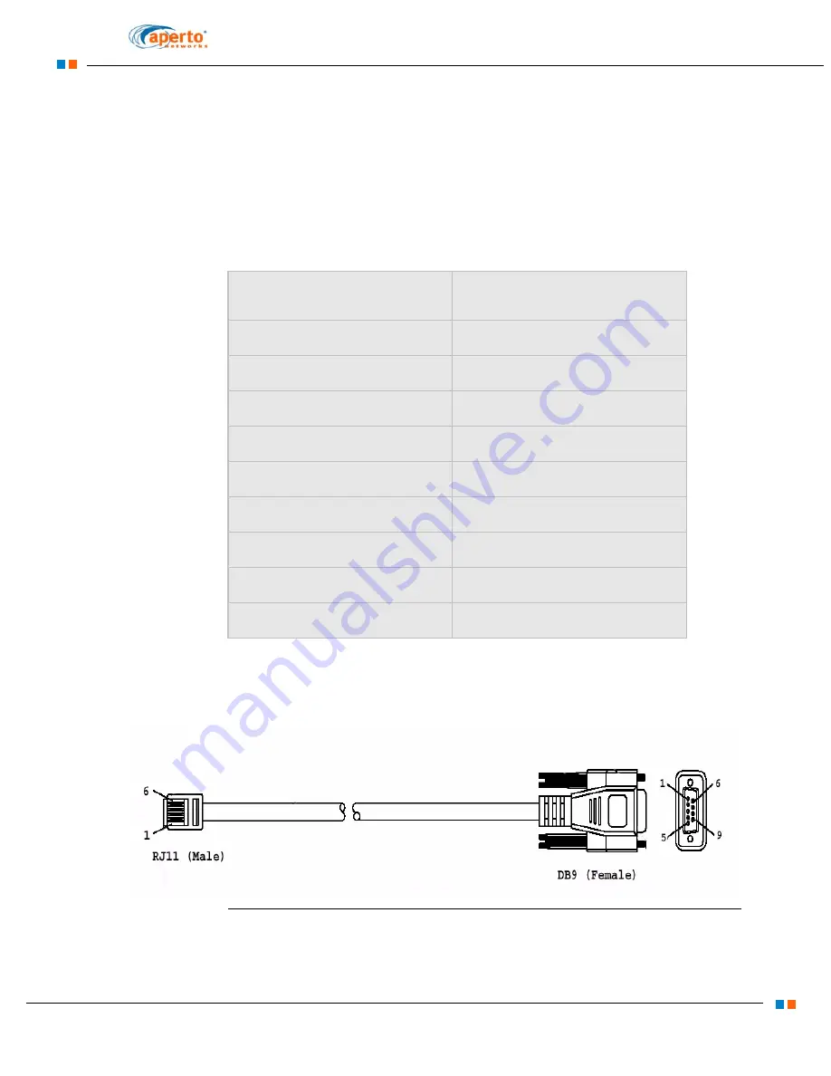
shows a DB 9 and RJ11 Cable Pin-out.
Figure 2-15
DB 9 (Female) and RJ 11 (Male) pinout
DB9 (Female) Connector on
computer
RJ11 (Male) Connector on the
MSC card
1
--
2
3
3
2
4
--
5
5
6
--
7
--
8
--
9
--
Содержание PacketMAX 5000
Страница 10: ...Preface Preface vi PacketMax 5000 Installation and Operation Manual 10007678 Rev J ...
Страница 14: ...Table Of Content TOC 4 PacketMax 5000 Installation and Operation Manual 10007678 Rev J ...
Страница 38: ...1 20 PacketMax 5000 Installation and Operation Manual 10007678 Rev J Chapter 1 Overview Of Base Station ...
Страница 64: ...2 26 PacketMax 5000 Installation and Operation Manual 10007678 Rev J Chapter 2 Base Station Components ...
Страница 104: ...5 16 PacketMax 5000 Installation and Operation Manual 10007678 Rev J Chapter 5 Commissioning the Base Station ...
Страница 114: ...A 10 PacketMax 5000 Installation and Operation Manual 10007678 Rev J Chapter A Event Reporting ...
Страница 124: ...C 6 PacketMax 5000 Installation and Operation Manual 10007678 Rev J Chapter C Cables Spares and Accessories ...
Страница 146: ...E 4 PacketMax 5000 Installation and Operation Manual 10007678 Rev J Chapter E Certifications ...
Страница 150: ...F 4 PacketMax 5000 Installation and Operation Manual 10007678 Rev J Chapter F Troubleshooting ...

