2–17
PacketMax 5000 Installation and Operation Manual, 10007678 Rev J
Chapter 2. Base Station Components
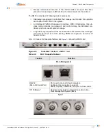
To remove the
MSC
cards safely for
hot swap
, follow the instructions below:
1.
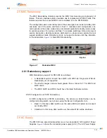
Push in BOTH ejector arms located at each end of the card (shown in
) and hold them until the blue H/S LED light turns ON.
2.
As soon as the LED light turns ON, gently pull back on both ejectors (but not
all they way back such that the card gets ejected) and wait until the blue H/S
LED light blinks. A blinking H/S LED signifies successful completion of the prior
steps.
If you wait too long to pull out both ejector arms, the cycle will abort and you will have
to repeat this step from the beginning.
3.
Push in and hold BOTH ejector arms on until the red OSS LED turns ON. At
this time, the card is ready to be safely removed from the PM5000 chassis.
Remove the card by pulling BOTH of the ejectors all the way out causing the
card to be removed from the system.
NOTE:
If you loose the sequence at any time, repeat again from Step 1.
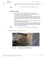
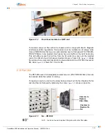
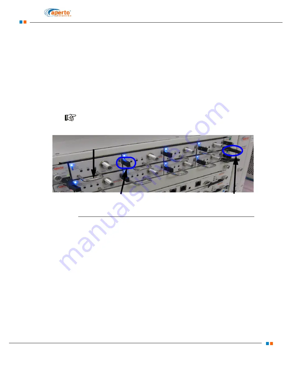
Figure 2-10
Ejector for hot swapping WSC Card
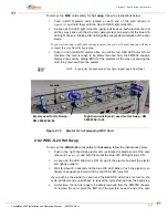
2.8.2 WSC-S-24 Hot Swap
To remove the
WSC-S-24
cards safely for
hot swap
, follow the instructions below:
1.
Push in the right hand side ejector arm (vertically) located at end of the card
(shown in
) and hold them until the blue H/S LED light turns ON.
2.
As soon as the LED light turns ON, let go off the ejector and pull the ejector
arm lightly outward.
3.
Wait for about 2-3 seconds till the blue H/S LED blinks. Push the ejector (ver-
tically) once again and wait until the red OSS LED turns ON.
If you push on the ejector too soon and the Red OOS LED does not turn on, the
cycle will abort and you will have to repeat the cycle starting from the beginning.
4.
At this time, the card is ready to be safely removed from the PM5000 chassis.
To remove the card, point the BOTH of the ejectors at each end of the card
1: H/S LED
2: Blinking H/S LED
3: OSS LED
Right hand side Ejector used for Hot Swap - PM
5000 WSC-S-24
Ejector used for Hot Swap-
PM 5000 WSC-48
Handle
Содержание PacketMAX 5000
Страница 10: ...Preface Preface vi PacketMax 5000 Installation and Operation Manual 10007678 Rev J ...
Страница 14: ...Table Of Content TOC 4 PacketMax 5000 Installation and Operation Manual 10007678 Rev J ...
Страница 38: ...1 20 PacketMax 5000 Installation and Operation Manual 10007678 Rev J Chapter 1 Overview Of Base Station ...
Страница 64: ...2 26 PacketMax 5000 Installation and Operation Manual 10007678 Rev J Chapter 2 Base Station Components ...
Страница 104: ...5 16 PacketMax 5000 Installation and Operation Manual 10007678 Rev J Chapter 5 Commissioning the Base Station ...
Страница 114: ...A 10 PacketMax 5000 Installation and Operation Manual 10007678 Rev J Chapter A Event Reporting ...
Страница 124: ...C 6 PacketMax 5000 Installation and Operation Manual 10007678 Rev J Chapter C Cables Spares and Accessories ...
Страница 146: ...E 4 PacketMax 5000 Installation and Operation Manual 10007678 Rev J Chapter E Certifications ...
Страница 150: ...F 4 PacketMax 5000 Installation and Operation Manual 10007678 Rev J Chapter F Troubleshooting ...

