2–2
PacketMax 5000 Installation and Operation Manual, 10007678 Rev J
Chapter 2. Base Station Components
2.1 PacketMAX Base Station
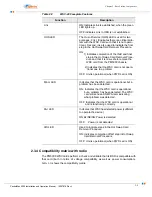
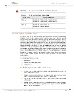
A PacketMax Base Station 5000 consists of the following components:
19 inch rack-mountable standard compliant ATCA chassis.
Either AC and DC power supply.
One or more Wireless System Controller Cards (QWCs)
-
Base Station Radio Connection
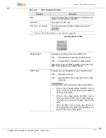
One or two (for redundancy) Main System Controller (MSC) Card.
-
Serial port for CLI management.
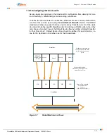
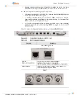
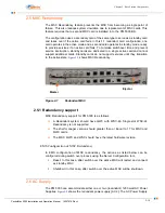
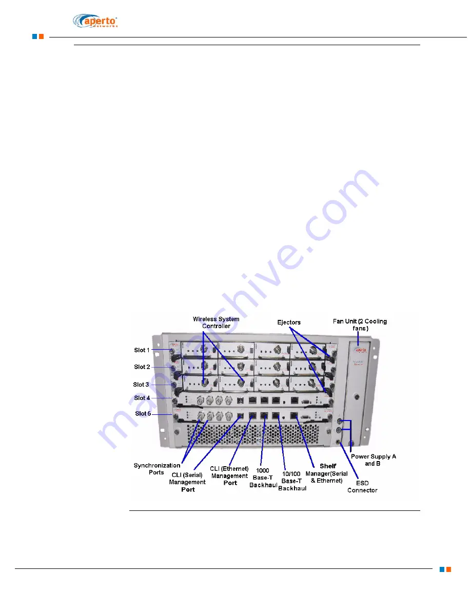
The Front Panel of the PacketMax 5000 has
Wireless System Controllers (WSC) and Main System Controllers (MSC) with
their ports and interfaces
Access to Modular Fan Unit
Access to Modular AC Power supplies at the bottom.
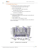
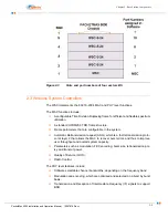
shows the front view of the a PacketMax 5000 picture, with two MSCs and
three WSC Cards installed.
Figure 2-1
PacketMax Interface for PacketMax 5000
Содержание PacketMAX 5000
Страница 10: ...Preface Preface vi PacketMax 5000 Installation and Operation Manual 10007678 Rev J ...
Страница 14: ...Table Of Content TOC 4 PacketMax 5000 Installation and Operation Manual 10007678 Rev J ...
Страница 38: ...1 20 PacketMax 5000 Installation and Operation Manual 10007678 Rev J Chapter 1 Overview Of Base Station ...
Страница 64: ...2 26 PacketMax 5000 Installation and Operation Manual 10007678 Rev J Chapter 2 Base Station Components ...
Страница 104: ...5 16 PacketMax 5000 Installation and Operation Manual 10007678 Rev J Chapter 5 Commissioning the Base Station ...
Страница 114: ...A 10 PacketMax 5000 Installation and Operation Manual 10007678 Rev J Chapter A Event Reporting ...
Страница 124: ...C 6 PacketMax 5000 Installation and Operation Manual 10007678 Rev J Chapter C Cables Spares and Accessories ...
Страница 146: ...E 4 PacketMax 5000 Installation and Operation Manual 10007678 Rev J Chapter E Certifications ...
Страница 150: ...F 4 PacketMax 5000 Installation and Operation Manual 10007678 Rev J Chapter F Troubleshooting ...

