


58
Change the System Setting — Digital Input &Output.
You may enable the
Digital Input
(D/I) and
Digital Output
(D/O) feature and configure the source of
events for your camera.
1. Click on the
DI and DO
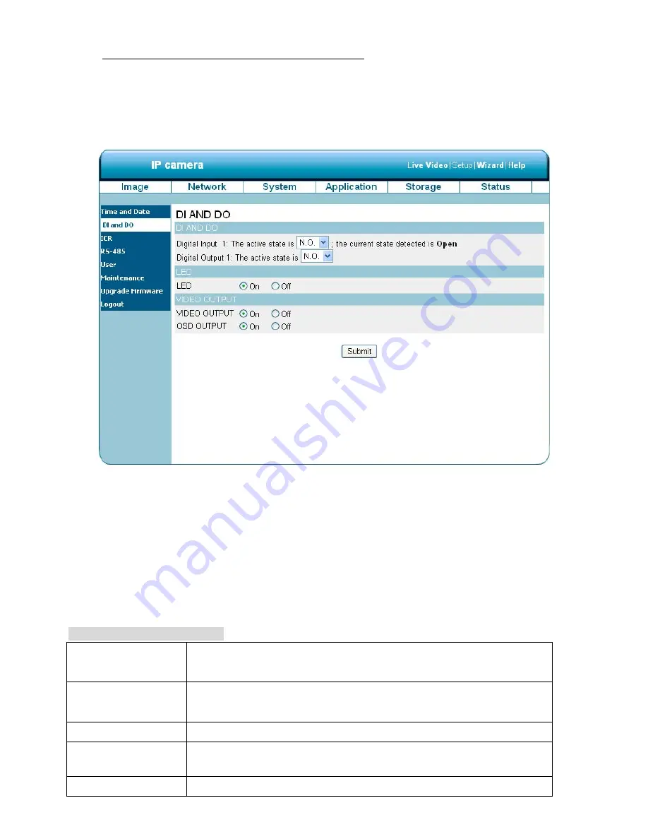
button on the left side of the “System” page to enter the “DI and DO” page.
2. Select the active state of the Digital Input 1 from the drop-down list.
3. Select the active state of the Digital Output 1 from the drop-down list.
4. Click to set the LED “On” or “Off’.
5. Click to set the VIDEO OUTPUT “On” or “Off’. Click to set the OSD OUTPUT “On” or “Off’.
6. Click on the
Submit
button to submit the new user’s setting.
Description of function keys:
Digital Input:
Select “N.O.” or “N.C.” as the active state of the Digital Input, in order to
use the GPIO connector function.
Digital Output:
Select “N.O.” or “N.C.” as the active state of the Digital Output, in order to
use the GPIO connector function.
LED
Select “ON” or “OFF” to use the item, which indicates a camera’s status.
VIDEO OUTPUT
Select “ON” or “OFF” to use the video out connecting port, to send out
analog signals.
OSD OUTPUT
Select “ON” or “OFF” to display the OSD when send out the signals.
Содержание LC-7513
Страница 2: ......
Страница 14: ...12 2 5 The Alarm wiring diagrams The LC 7513 IP Box Camera PoE ALM i ALM o 485 485 DC o GND 12V 12V ...
Страница 15: ...13 The LC 7523 7533 Fixed IP Indoor Outdoor Mini Dome PoE GND 12V Di Di Do Do 12V 12V ...
Страница 16: ...14 The LC 7553 Bullet IP Camera Indoor Outdoor PoE GND 12V Di Di Do Do 12V 12V ...
Страница 82: ...80 drop down list on the Application Event page ...


