Appostar KP-5374 Скачать руководство пользователя страница 25

BOARD SETTING


KP-5374 Touch POS Terminal

 21 

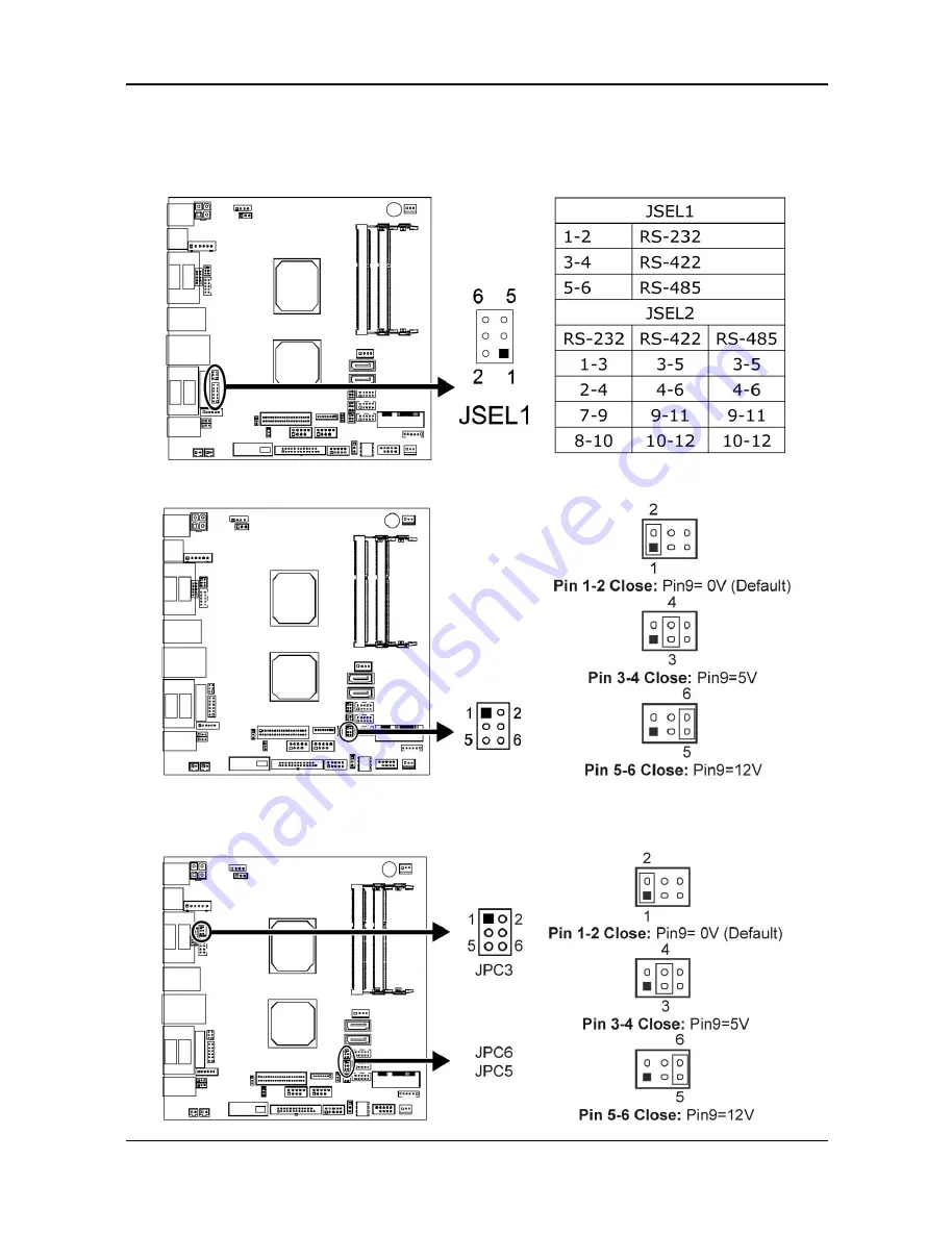
Serial Port Connectors & Headers:   

JSEL1/JSEL2: RS-232/422/485 Switch Headers for COM1 (optional)     

The headers determine that COM1 belongs to RS-232 (Default), 422, or 485.   

JPC4: Serial Port Voltage Switch Jumper for JCOM4


JPC3/JPC5/JPC6: Serial Port Voltage Switch Jumpers for 

JCOM3/JCOM5/JCOM6


All manuals and user guides at all-guides.com

Содержание KP-5374

Страница 1: ...KP Touc User Edition A 537 ch PO r s M Apr 2014 74 OS Ter Manu rmina ual al http www appostar com Version m 1 0 All manuals and user guides at all guides com a l l g u i d e s c o m...

Страница 2: ...t isposed o f their wa recycling ut where t city office product ommiss and found t 15 of th protection pment ge talled and interferen that interf es cause e determ try to cor eceiving a etween th to...

Страница 3: ...ght to make improvements to this publication from time to time in the contents hereof without obligation of the manufacturer to notify any person of such revision or changes Copyright This work is cop...

Страница 4: ...ning flammable gas inside or around the product 7 Do not allow foreign objects or liquids to enter the product serious damage may result 8 Do not place the product on an unstable surface The product m...

Страница 5: ...ware Installation 9 2 1 Peripheral Installation 9 2 2 Component Installation 15 CHAPTER 3 Software Installation 17 3 1 Motherboard Driver Installation 17 3 2 Peripheral Device Driver Installation 18 C...

Страница 6: ...s n The KP ch with th ing items act the de 2 Quick 5 vervie 5374 is t omers de up in a co rtical bas r its uniqu the syste P 5374 is e tone of s are cont ealer from k Referenc Power Co ew the cost e e...

Страница 7: ...w B MSR Cable manag cover ouch POS T pearan ew w Base cover gement Terminal ce P PRODUCT O 15 L touc Front Cust disp MS Rear OVERVIEW 3 LCD h panel panel tomer play cover R cover r cover W r All manua...

Страница 8: ...PRODUCT 4 Side View Left Righ T OVERVIEW w Side t Side I O with W h cover KP 5374 T I O with Touch POS hout cove Terminal r All manuals and user guides at all guides com...

Страница 9: ...PRODUCT OVERVIEW KP 5374 Touch POS Terminal 5 1 3 I O Interface All manuals and user guides at all guides com...

Страница 10: ...passive stereo speaker x 2 USB USB 2 0 A type Connector x 4 Control Interface No Name Description USB USB 2 0 A type Connector HDD LED Indicator Indicates the operational status of the Hard Disk Driv...

Страница 11: ...x RJ11 with DC 12V Default 24V Keyboard Port 1 x PS 2 Keyboard Mouse VGA Port 1 x DB15 VGA Audio Jack 1 x Mic in 1x Line out Speaker 2 x Integrated 1 5 W stereo speaker Ethernet Port 1 x RJ45 10M 100M...

Страница 12: ...l Environment EMC Safety CE FCC Class A Operating Temperature 5 C 40 C Storage Temperature 20 C 60 C Operating Humidity 15 80 RH Storage Humidity 20 90 RH Mechanical Housing Color Black Construction A...

Страница 13: ...in e of KP 5 he MSR ca t work p ware I are config disconnec llation e Read stalled in 5374 able roperly p Instal guration cted to pr er MSR Step MSR e Step 3 with 2 please ref llation ensure th revent...

Страница 14: ...ATION ted LCD he custom 2 thumb s re 2 b D VFD C mer displa screws of Fi Custom ay cover o ff the rea igure 2 mer Disp on the ma r cover by a KP 5374 T play Ins ain unit y a coin Figure Touch POS stal...

Страница 15: ...to the COM 6 port with DC 5V on the I O board as shown in the picture Figure 2 f Figure 2 d Figure 2 e Figure 2 f Figure 2 g Step 4 Cover the screw holes with plastic lids and reinstall the rear cove...

Страница 16: ...top hin ure 3 d y Instal o its horiz managem the 2 thu igure 3 b nge cover Fi llation zontal po ment and umb scre b 3 c r using a igure 3 sition F the custo ws off bo screwdriv a KP 5374 T igure 3 a...

Страница 17: ...nge co er hinge c 3 j gure 3 i th 4 scre ure that t g over and t cover to th Fi ews Fit th the 4 con the upper he second igure 3 he second nection p r hinge co d display a h HARDWA d display o points...

Страница 18: ...isp eshooting ATION he VGA ca r output he front gure 3 l play does g ble to the DC jack the rear n t work Fi e VGA por Figure and the properly igure 3 rt DB15 3 k cable ma please re k KP 5374 T and th...

Страница 19: ...humb sc ure 4 c 4 screws f w one allation HDD panel to it mb screw TA 1 and S rew that from the Fi Fi n ts horizon ws off the SATA pow holds the HDD brac igure 4 igure 4 ntal positi front cov wer cabl...

Страница 20: ...4 e 4 f Figure 4 e Figure 4 f 2 2 2 Mini PCI Express Card Installation Step 1 Unfasten 2 thumb screws off the rear cover by a coin Figure 5 a 5 b Figure 5 a Figure 5 b Step 2 Locate the Mini PCI Expre...

Страница 21: ...e Appostar Driver Installer appears on the screen If not locate the Setup exe file at CD and double click it to execute the one step driver installation Follow the on screen instructions to complete t...

Страница 22: ...Click Next on the Welcome screen to continue c Uncheck the Install PS 2 interface driver option Click Next to continue d Select the Install RS232 interface driver option Click Next to continue e Selec...

Страница 23: ...ect the Destination Folder or use the default one listed h Type a Folder name or use the default one listed Click Next to continue i A progress window appears Please wait j Click Yes The installation...

Страница 24: ...rd Jumper Setting NOTE represents thest 1 pin JCMOS1 Clear CMOS Jumper Placing the jumper on pin2 3 allows user to restore the BIOS safe setting and the CMOS data Please carefully follow the procedure...

Страница 25: ...2 RS 232 422 485 Switch Headers for COM1 optional The headers determine that COM1 belongs to RS 232 Default 422 or 485 JPC4 Serial Port Voltage Switch Jumper for JCOM4 JPC3 JPC5 JPC6 Serial Port Volta...

Страница 26: ...5374 Touch POS Terminal JP2 Voltage Switch Jumper for Cash Draw Connector This jumper is for controlling the Pin4 of RJ11 JRJ11 to switch 12V or 24V All manuals and user guides at all guides com a l...

Страница 27: ...reset the system If the problem remains unsolved contact your dealer for further assistance The Touch Panel is not working properly 1 Check whether the Touch Panel driver has been correctly installed...

Страница 28: ...reset to VGA LVDS as factory default 4 Check the Display Setting 1 Right click on the desktop and click Properties 2 Select the Settings tab and you will see monitor 1 and monitor 2 3 Click monitor 2...

Отзывы: