background image

10. OPERATION:

A.

The receptacle can now be turned to the "ON" position by lifting the operating handle (11) to the upper-most position.

Please note that the receptacle can be turned "ON" with or without a mating plug engaged.

Safety feature 

- The receptacle is interlocked to the operating handle mechanism so that a mating plug

may not be inserted or removed when the switch is in the "ON" position.

B. A hole is provided in the housing lock-out (12) and operating handle (11) for the use of a padlock

(  See "FIGURE C") to prevent unauthorized movement of the operating handle (11) f

r

om the "OFF" position. 

11. MAINTENANCE:

A. INSPECTION:

Receptacle must be inspected regularly. Schedule of inspections is determined by f

r

equency 

of use and environmental conditions. 

• It is recommended that inspections be carried out at least once a year.

WARNING 

If any parts of the "WSR" unit or the mating plug appear to be 

missing, broken or show signs of damage: 

DISCONTINUE USE IMMEDIATELY! 

This condition could cause serious/fatal personal injury due to 

electrocution and/or equipment damage. Repair with the proper 

re  lacement  art s  before continuin  service. 

DURING THE INSPECTIONS, PERFORM AT LEAST THE FOLLOWING: 

1 .  Electrical power must be turned "OFF" before performing maintenance. 

2 .  Inspect all conductor terminations for secureness. 

• Retorque to values given previously in these instructions.

• Discoloration due to excessive heat is an indication of possible problems and should be thoroughly

investigated and repairs made as necessary.

3 .  Check grounding and bonding effectiveness/continuity. 

Retorque connections to original values.

4 .. Check gaskets for damage. Replace as necessary. 

5 .. Clean interior of all foreign materials. 

6. Cover bolts (2) must be tightened to 25  -30  lbs .. -ft. torque ..

7 .  Make sure that receptacle assembly flip-cover (13) seals cover to receptacle housing face, if applicable.

8 .  If applicable, make sure that receptacle assembly screw cover (21) seals cover to receptacle housing face.

9 .. Make sure the receptacle assembly nameplate located on the outside of the cover remains clean and legible.

Do not paint nameplate.

• It is recommended that an electrical preventive maintenance program,

such as found in the National Fire Protection Bulletin NFP A no. 70B,

be followed in addition to the above.

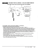
B. DISCONNECT SWITCH AND HANDLE ASSEMBLY:

Disconnect switches occasionally fail with use and need to be replaced .. The disconnect switch utilized in this

receptacle can be replaced with the same type and brand as factory installed. Doing so will not affect the U/L listing .

To remove disconnect switch from housing 

-

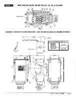
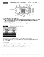
• Referring to "FIGURE C", remove the two handle lock-out screws (18) and remove housing lock-out (12) by lifting

it off of unit.

• Remove operating handle (11) from disconnect switch mechanism assembly (20) by carefully lifting off of assembly.

• Loosen the line side lug screws (7) of the disconnect switch and remove line side wi

r

es from the switch (15).. 

• Loosen the load side lug screws (9) of the disconnect switch and remove wi

r

es from the switch (1.5). Please take 

note of the orientation of these wires for proper reassembly.  Also note that the wires (8) that connect the 

receptacle to either the disconnect switch directly for the non-fused switches,  or connect the receptacle 

to the fuse block lugs (10) for the fuse switches are numbered according to phase location (See "FIGURE B") 

• Remove disconnect switch and fuse base (  if applicable) mounting screws (17) . Remove disconnect switch (15)

and fuse base ( if applicable) (16) from housing (5).

Page 6 

330118 

Rev.  A 

3/28/95 

Содержание WSR Series

Страница 1: ...s may result in serious fatal personal injury from electrocution TABLE A HORSEPOWER RATING FIGURE A Except as expressly provided by Appleton Electric Company Appleton in writing Appleton products are intended for ultimate purchase by industrial users and for operation by persons trained and experienced in the use and maintenance of this equipment and not for consumers or consumer use Appleton warr...

Страница 2: ...90 1 375 60 CPH6034BC 875 1 906 100 ACP1034CD from the elements NEMA Type 3 3R or 12 for the units that _________ have the receptacle flip cover installed and NEMA Type 3 3R 4 4X 12 that have the screw cover installed 60 100 Ampere only Enclosure cover is gasketted to seal cover against the enclosure housing The receptacle face of the 60 100 Ampere units is threaded to allow mating plugs to thread...

Страница 3: ...EW WITH COVER REMOVED UNIT SHOWN IS CATALOG NUMBER WSR6352 I 2 1 c e hc 2 Z lla 7 57 0 4 CATALOG ER CCf OUIT ENTRY r 1 1 11 00 27 9 CM WSR3352 WSR33342 WSR6352 WSR63542 WSRI03342 WSR10332 DIMENSION A 19 23 48 90 CM l 22 88 38 11 CM l A 330118 Rev A 3 28 95 Page 3 ...

Страница 4: ... housing cover bolts 2 but do not attempt to remove them completely from the cover 3 because they are designed to be captive B The cover 3 is now free to swing open on its factory installed hinges 4 C Although it is not necessary the cover 3 can be removed fr om the housing 5 by carefully lifting the cover enough to clear the hinge pins approximately 90 inches D It is recommended that if removed t...

Страница 5: ...nterior of all foreign materials 6 Cover bolts 2 must be tightened to25 30 lbs ft torque 7 Make sure that receptacle assembly flip cover 13 seals cover to receptacle housing face if applicable 8 Ifapplicable make sure that receptacle assembly screw cover 21 seals cover to receptacle housing face 9 Make sure the receptacle assembly nameplate located on the outside of the cover remains clean and leg...

Страница 6: ...no unwanted opens shorts or grounds Do not apply power until the following steps are completed A Test to verify correct phasing and ground connections B Test insulation resistance by meggering high voltage or hi pot test to be sur e the system does not have any short cir cuits or unwanted grounds 7 CLEAN COVER AND HOUSING Before closing the cover 3 it is str ongly recommended that all dirt debris ...

Страница 7: ...i JJ 1 Ii PW t WSRNT30F WSR3352 WSRNT30U WSR33542 WSRNT60F WSR6352 WSRNT60U WSR63542 WSRNTlOOF WSR10352 WSRNTlOOU WSR103542 Replace existing operating handle 11 with new one provided with disconnect switch group Re assemble housing lock out 12 and the two handle lock out screws 18 to housing 5 and tighten screws to 20 25 lb in torque C GROUND LUG Referring to FIGURE C loosen the ground lug screw a...

Страница 8: ...sm assembly 2 down onto the line base assembly 3 until the tabs in the line base assembly lock into the corresponding holes in the mechanism assembly 2 Make sure switch mechanism 4 engages with switch pivot arm 5 Assemble the arc suppressor assembly 6 onto the line base assembly 3 with the arc suppressor retaining screw 7 provided For 30 60 Ampere fusible switches only Assemble fuse clips 8 to swi...

Страница 9: ...cement parts To replace the receptacle assembly Referring to FIGURE C loosen the load side lug screws 9 ofthe disconnect switch 1 5 or fuse base 16 if applicable and remove wires Remove the four 4 receptacle assembly mounting screws 14 that fasten the assembly to the housing 5 Support the assembly so that it does not fall from unit Remove the old receptacle assembly and replace it with the new uni...

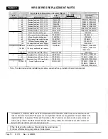
Страница 10: ...mp 3w 4p WRDK1034 30 60 100 Ground lug screw assy 59350996000 WSR3352 WSR33542 WSR6352 WSR63542 WSR6352 WSR63542 WSR10352 WSR103542 WSR10352 WSR103542 WSR3352 WSR33542 WSR6352 WSR63542 WSR10352 WSR103542 WSR3352 WSR33542 WSR6352 WSR63542 WSR103542 WSR10352 WSR3352 WSR33542 WSR6352 WSR63542 WSR10352 WSR103542 WSR3352 WSR33542 WSR6352 WSR63542 WSR10352 WSR103542 Note For electrical interlock install...

Отзывы: