background image

330118

lliJ-------I

N_s_r_R_u_c_r_1o_N_S_H_E�ET

COMPANY 

Instruction for Installation, Operation and Maintenance 

of 

11

WSR

11 

Interlocked Receptacles: 30, 60 & 100 Ampere 

"WSR" SERIES: 

Heavy  duty  single  throw  safety  switch  with  interlocked 

Appleton Powertite

® 

compatible receptacle . 

COMPLIANCES: 

UL. Listed, File No. 145917 

UL498 - Attachment Plugs and Receptacles 

UL98 - Enclosed and Dead-Front Switches 

UL50 •· Enclosures for Electrical Equipment 

NEC wire bending space, Table 373-6(b). 

ELECTRICAL RATINGS: 

Maximum Voltage: 600VAC at 60 Hz, 250 VDC 30, 60 or 100 

Amperes, depending on current rating of product 

( See product nameplate  for details ) 

Read instructions carefully and with full  understanding for 

safe installation and operation.. 

STANDARD FEATURES: 

• Epoxy coated finish on receptacle and disconnect

switch housing.

• Current carrying parts in housing are all plated copper

• Lugs ·· front removable, standard mechanical lugs on

incoming line .. L.ay-•in ground lug.

• Screw cover assembly provided for 60 & 100 Ampere

units which can be used on receptacle housing,

instead of flip cover assembly to meet certain environ

mental conditions ..

OPTIONS: 

• Electrical Interlocks -1 N.O., 1 N. C. or 2 NO, 2 N .. C.

MODIFICATION WARNING 

Do not modify these devices in anyway ..  Replace any missing 

or  broken  parts  with  the  proper  replacement  parts  from 

Appleton Electric. Modification of these devices or substitution 

of  parts  with  non-standard  parts  may  result  in  serious/fatal 

personal injury from electrocution. 

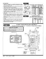
TABLE  A 

HORSEPOWER RATING: 

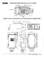
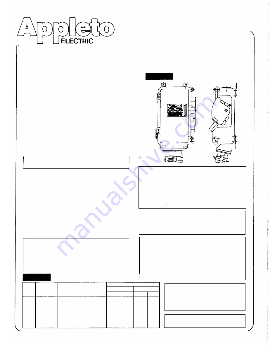
FIGURE A 

Except  as  expressly  provided  by  Appleton  Electric 

Company  (Appleton)  in  writing,  Appleton  products  are 

intended for ultimate purchase by  industrial users and for 

operation by  persons trained and experienced in the use 

and maintenance of this equipment and not for consumers 

or consumer use .. Appleton warranties do not extend to, and 

no  reseller  is  authorized to extend  Appleton's  warranties  to, 

any consumer. 

ELECTRICAL WARNING 

Electrical  power  must  be  turned 

OFF 

before  and  during 

installation and maintenance. 

Failure to do so m ay result 

in serious 

fatal injuries due  to  electrocution. 

DAMAGE WARNING 

If any parts of the "WSR" unit or the mating plug appear to be 

missing, broken or show signs of damage: 

DISCONTINUE USE  IMMEDIATELY 

This condition could cause serious/fatal personal injury due to 

electrocution and/or equipment damage. Repair replacement 

part(s)  before  continuing  service  with  the  proper  replace­

ment part(s) before continuing service 

HORSEPOWER RATINGS 

WARNING 

DC 

AC 

CA1ALOG 

SWITCH 

AC 

DC 

VOLTS  VOLTS  AMP 

NUMBERS 

TYPE 

STAND.  MAX.  STAND.  MAX. 

250  600 

30 

WSR3352 

FUSED 

7.5 

20 

---

250  600 

30 

WSR33542 

NON-FUSED 

...... 

20 

---

250  600 

60 

WSR6352 

FUSED 

15 

50 

10 

-·--

250  600 

60 

WSR63542 

NON-FUSED 

---

50 

--·-

10 

250  600  100 

WSR10352 

FUSED 

30 

75 

20 

---

250  600  100 

WSR103542 

NON-FUSED 

-·--

75 

....... 

20 

The 

"WSR" 

receptacles are designed and 

tested for use with copper conductors only. 

DO  NOT 

use aluminum  wiring,as dangerous 

overheating and fire may result. 

WARNING 

Not suitable for use  as service  equipment. 

Rev.  A  3/29/95 

Page 1 

Содержание WSR Series

Страница 1: ...s may result in serious fatal personal injury from electrocution TABLE A HORSEPOWER RATING FIGURE A Except as expressly provided by Appleton Electric Company Appleton in writing Appleton products are intended for ultimate purchase by industrial users and for operation by persons trained and experienced in the use and maintenance of this equipment and not for consumers or consumer use Appleton warr...

Страница 2: ...90 1 375 60 CPH6034BC 875 1 906 100 ACP1034CD from the elements NEMA Type 3 3R or 12 for the units that _________ have the receptacle flip cover installed and NEMA Type 3 3R 4 4X 12 that have the screw cover installed 60 100 Ampere only Enclosure cover is gasketted to seal cover against the enclosure housing The receptacle face of the 60 100 Ampere units is threaded to allow mating plugs to thread...

Страница 3: ...EW WITH COVER REMOVED UNIT SHOWN IS CATALOG NUMBER WSR6352 I 2 1 c e hc 2 Z lla 7 57 0 4 CATALOG ER CCf OUIT ENTRY r 1 1 11 00 27 9 CM WSR3352 WSR33342 WSR6352 WSR63542 WSRI03342 WSR10332 DIMENSION A 19 23 48 90 CM l 22 88 38 11 CM l A 330118 Rev A 3 28 95 Page 3 ...

Страница 4: ... housing cover bolts 2 but do not attempt to remove them completely from the cover 3 because they are designed to be captive B The cover 3 is now free to swing open on its factory installed hinges 4 C Although it is not necessary the cover 3 can be removed fr om the housing 5 by carefully lifting the cover enough to clear the hinge pins approximately 90 inches D It is recommended that if removed t...

Страница 5: ...nterior of all foreign materials 6 Cover bolts 2 must be tightened to25 30 lbs ft torque 7 Make sure that receptacle assembly flip cover 13 seals cover to receptacle housing face if applicable 8 Ifapplicable make sure that receptacle assembly screw cover 21 seals cover to receptacle housing face 9 Make sure the receptacle assembly nameplate located on the outside of the cover remains clean and leg...

Страница 6: ...no unwanted opens shorts or grounds Do not apply power until the following steps are completed A Test to verify correct phasing and ground connections B Test insulation resistance by meggering high voltage or hi pot test to be sur e the system does not have any short cir cuits or unwanted grounds 7 CLEAN COVER AND HOUSING Before closing the cover 3 it is str ongly recommended that all dirt debris ...

Страница 7: ...i JJ 1 Ii PW t WSRNT30F WSR3352 WSRNT30U WSR33542 WSRNT60F WSR6352 WSRNT60U WSR63542 WSRNTlOOF WSR10352 WSRNTlOOU WSR103542 Replace existing operating handle 11 with new one provided with disconnect switch group Re assemble housing lock out 12 and the two handle lock out screws 18 to housing 5 and tighten screws to 20 25 lb in torque C GROUND LUG Referring to FIGURE C loosen the ground lug screw a...

Страница 8: ...sm assembly 2 down onto the line base assembly 3 until the tabs in the line base assembly lock into the corresponding holes in the mechanism assembly 2 Make sure switch mechanism 4 engages with switch pivot arm 5 Assemble the arc suppressor assembly 6 onto the line base assembly 3 with the arc suppressor retaining screw 7 provided For 30 60 Ampere fusible switches only Assemble fuse clips 8 to swi...

Страница 9: ...cement parts To replace the receptacle assembly Referring to FIGURE C loosen the load side lug screws 9 ofthe disconnect switch 1 5 or fuse base 16 if applicable and remove wires Remove the four 4 receptacle assembly mounting screws 14 that fasten the assembly to the housing 5 Support the assembly so that it does not fall from unit Remove the old receptacle assembly and replace it with the new uni...

Страница 10: ...mp 3w 4p WRDK1034 30 60 100 Ground lug screw assy 59350996000 WSR3352 WSR33542 WSR6352 WSR63542 WSR6352 WSR63542 WSR10352 WSR103542 WSR10352 WSR103542 WSR3352 WSR33542 WSR6352 WSR63542 WSR10352 WSR103542 WSR3352 WSR33542 WSR6352 WSR63542 WSR103542 WSR10352 WSR3352 WSR33542 WSR6352 WSR63542 WSR10352 WSR103542 WSR3352 WSR33542 WSR6352 WSR63542 WSR10352 WSR103542 Note For electrical interlock install...

Отзывы: