APOGEE INSTRUMENTS, INC.
| 721 WEST 1800 NORTH, LOGAN, UTAH 84321, USA
TEL: (435) 792-4700 | FAX: (435) 787-8268 | WEB: APOGEEINSTRUMENTS.COM
Copyright © 2021 Apogee Instruments, Inc.
OWNER’S MANUAL
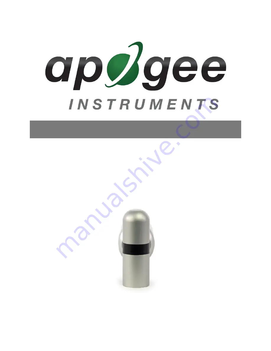
ALBEDOMETER
Model SP-722-SS
Rev: 1-Jun-2021
Страница 1: ...STRUMENTS INC 721 WEST 1800 NORTH LOGAN UTAH 84321 USA TEL 435 792 4700 FAX 435 787 8268 WEB APOGEEINSTRUMENTS COM Copyright 2021 Apogee Instruments Inc OWNER S MANUAL ALBEDOMETER Model SP 722 SS Rev 1 Jun 2021 ...
Страница 2: ...te of Compliance 3 Introduction 4 Sensor Models 4 Specifications 6 Deployment and Installation 7 Cable Connectors 8 Operation and Measurement 8 Maintenance and Recalibration 14 Troubleshooting and Customer Support 16 Return and Warranty Policy 17 ...
Страница 3: ...ctrical and electronic products with respect to the restriction of hazardous substances Please be advised that based on the information available to us from our raw material suppliers the products manufactured by us do not contain as intentional additives any of the restricted materials including lead see note below mercury cadmium hexavalent chromium polybrominated biphenyls PBB polybrominated di...
Страница 4: ...ackbody thermopile pyranometers traceable to the world radiation reference in Davos Switzerland Specifications for both models compare favorably to specifications for World Meteorological Organization WMO moderate and good quality classifications and specifications for International Organization of Standardization ISO Class C and Class B classifications Typical applications of pyranometers include...
Страница 5: ...ard looking and downward looking pyranometer to measure shortwave radiation Both individual sensors are available as stand alone sensors Model Signal SP 722 Modbus SP 710 Analog Sensor model number and serial number are located on the bottom of the sensor If you need the manufacturing date of your sensor please contact Apogee Instruments with the serial number of your sensor Upward looking Pyranom...
Страница 6: ... reference standards are calibrated to the World Radiometric Reference WRR SP 722 SS Upward looking SP 722 SS Downward looking ISO 9060 2018 Class C N A Power Supply 5 5 to 24 V Current Draw Heaters off 5 mA Heaters on 31 mA Calibration Uncertainty 5 see Calibration Traceability below Measurement Range 0 to 2000 W m 2 shortwave irradiance Measurement Repeatability Less than 1 Long term Drift Non s...
Страница 7: ...he southern hemisphere Azimuth error is typically less than 0 5 but it is easy to minimize by proper cable orientation In addition to orienting the cable to point toward the nearest pole the sensor should also be mounted such that obstructions e g weather station tripod tower or other instrumentation do not shade the sensor Once mounted the green caps should be removed from the sensor The green ca...
Страница 8: ...tact Apogee directly to ensure ordering the proper pigtail configuration Alignment When reconnecting a sensor arrows on the connector jacket and an aligning notch ensure proper orientation Disconnection for extended periods When disconnecting the sensor for an extended period of time from a station protect the remaining half of the connector still on the station from water and dirt with electrical...
Страница 9: ...2 net radiometers For questions on the implementation of this protocol please refer to the official serial line implementation of the Modbus protocol http www modbus org docs Modbus_over_serial_line_V1_02 pdf 2006 and the general Modbus protocol specification http www modbus org docs Modbus_Application_Protocol_V1_1b3 pdf 2012 Further information can be found at http www modbus org specs php Overv...
Страница 10: ...t According to the Modbus protocol specification Holding Registers the type registers Apogee sensors contain are defined to be 16 bits wide However when making scientific measurements it is desirable to obtain a more precise value than 16 bits allows Thus several Modbus implementations will use two 16 bit registers to act as one 32 bit register Apogee Modbus sensors use this 32 bit implementation ...
Страница 11: ... version Integer Registers 44 Incident calibrated output watts shifted one decimal point to the left 45 Reflected calibrated output watts shifted one decimal point to the left 46 Incident detector millivolts shifted three decimal points to the left 47 Reflected detector millivolts shifted three decimal points to the left 48 Albedo reflected incident shifted one decimal point to the left 49 Reserve...
Страница 12: ... parity 0 none 1 odd 2 even 59 number of stopbits 60 incident multiplier shifted two decimal points to the left 61 Incident mV offset shifted two decimal points to the left 62 reflected multiplier shifted two decimal points to the left 63 Reflected mV offset shifted two decimal points to the left 64 Running average 65 Heater on off Registers marked with an asterisk cannot be written to unless a sp...
Страница 13: ...function code 0x3 reading register address 0 Each pair of square brackets indicates one byte Slave Address Function Starting Address High Byte Starting Address Low Byte No of Registers High Byte No of Registers Low Byte CRC High Byte CRC Low Byte 0x01 0x03 0x00 0x00 0x00 0x02 0xC4 0x0B An example of a data packet sent from the controller to the sensor using function code 0x10 writing a 1 to regist...
Страница 14: ...bration It determines total shortwave radiation incident on a horizontal surface at any time of day at any location in the world It is most accurate when used near solar noon in spring and summer months where accuracy over multiple clear and unpolluted days is estimated to be 4 in all climates and locations around the world For best accuracy the sky must be completely clear as reflected radiation ...
Страница 15: ... middle of page and an estimate of total shortwave radiation is returned on right hand side of page Homepage of the Clear Sky Calculator Two calculators are available One for pyranometers total shortwave radiation and one for quantum sensors photosynthetic photon flux density ...
Страница 16: ...ace the cable length from the sensor to the controller should be kept short no longer than 20 meters For more information see section 3 3 5 in this document http www modbus org docs Modbus_over_serial_line_V1_02 pdf RS 485 Cable Length If using an RS 485 serial interface longer cable lengths may be used The trunk cable can be up to 1000 meters long The length of cable from the sensor to a tap on t...
Страница 17: ...r factory The warranty does not cover equipment that has been damaged due to the following conditions 1 Improper installation or abuse 2 Operation of the instrument outside of its specified operating range 3 Natural occurrences such as lightning fire etc 4 Unauthorized modification 5 Improper or unauthorized repair Please note that nominal accuracy drift is normal over time Routine recalibration o...
Страница 18: ...anship Apogee Instruments will repair or replace the items free of charge If it is determined that your product is not covered under warranty you will be informed and given an estimated repair replacement cost PRODUCTS BEYOND THE WARRANTY PERIOD For issues with sensors beyond the warranty period please contact Apogee at techsupport apogeeinstruments com to discuss repair or replacement options OTH...