VITAM-9XXA Series User Manual
42
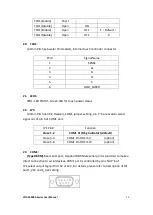
1
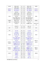
DCD# (Data Carrier Detect)
2
RXD (Received Data)
3
TXD (Transmit Data)
4
DTR (Data Terminal Ready)
5
Ground
6
DSR (Data Set Ready)
7
RTS (Request To Send)
8
CTS (Clear To Send)
9
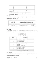
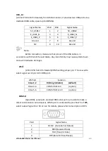
JP6 Setting:
Pin1-2 : RI (
Ring Indicator
) (default)
Pin3-4 : 5V Standby power
(
option
)
Pin5-6:12V Standby power (option)
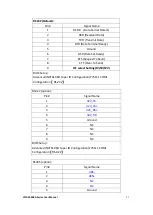
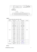
COM_6:
(2.0mm Pitch 2X5 Pin Header), COM6 Port, up to one standard RS232 port
is provided. It can be used directly via COM cable connection.
Signal Name
Pin#
Pin#
Signal Name
DCD
1
2
RXD
TXD
3
4
DTR
Ground
5
6
DSR
RTS
7
8
CTS
JP6 Setting:
RI/5V/12V
9
10
NC
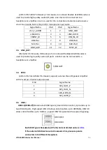
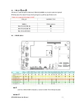
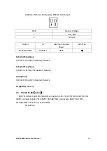
PS_ON1:
(2.0mm Pitch 1x2 Pin Wafer), ATX Power and Auto Power on jumper
setting
PS_ON
Mode
Close 1-2
Auto Power on (default)
Close 1-2
ATX Power
PS_ON2 (option):
(2.0mm Pitch 1x2 Pin Wafer)
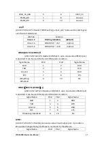
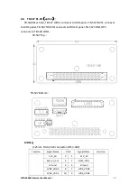
S1:
PWR BT: POWER on/off Button,
it is used to connect power switch
button. The two pins are disconnected under normal condition. You may short them
temporarily to realize system startup & shutdown or awaken the system from sleep
state.
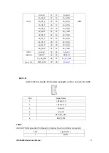
PWR LED:
POWER LED status.
Содержание VITAM-9 A Series
Страница 21: ...VITAM 9XXA Series User Manual 20 Unit mm Figure 2 1 Motherboard Dimensions ...
Страница 106: ...VITAM 9XXA Series User Manual 105 the installation Step4 Click Next to continue ...
Страница 107: ...VITAM 9XXA Series User Manual 106 Step5 Click Finish to complete the installation ...
Страница 112: ...VITAM 9XXA Series User Manual 111 Step10 Click Finish to complete the installation ...
Страница 116: ...VITAM 9XXA Series User Manual 115 Step6 Click Finish to complete installation ...


