


APC-3x84B/APC-3x85B User Manual
23
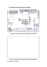
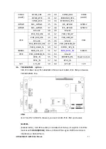
8. LED3/LED4
(
NC
)
:
LED3: Reserve.
LED4: Reserve.
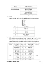
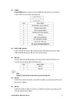
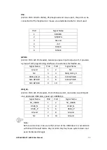
9. DC_IN1:
(5.08mm Pitch 1x3 Pin Connector), DC9V~36V System power input connector.
Pin#
Power input
1
DC+9V~36V
2
Ground
3
FG
Model
DC_IN1
SBC-7111-E3845-4G
180°Connector
SBC-7111-N2930-2G
180°Connector
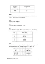
10. BT1/BT2:
Power on/off button
, They are used to connect power switch button. The two
pins are disconnected under normal condition. You may short them
temporarily to realize system startup & shutdown or awaken the system from
sleep state.
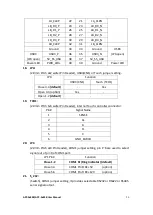
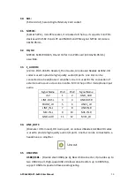
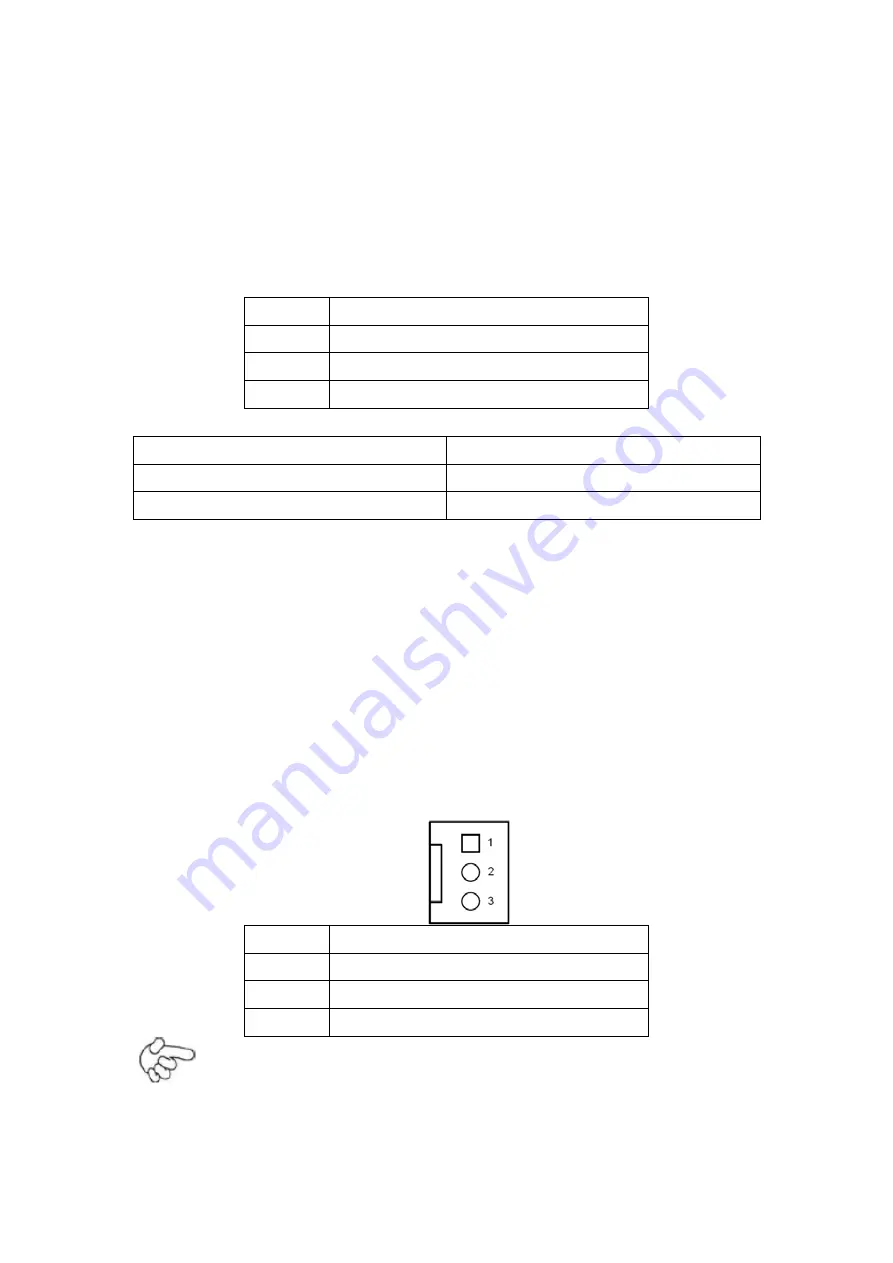
11. FAN1(option):
(2.54mm Pitch 1x3 Pin Header), Fan connector, cooling fans can be connected
directly for use. You may set the rotation condition of cooling fan in menu of
BIOS CMOS Setup.
Pin#
Signal Name
1
Ground
2
VCC
3
Rotation detection
Note:
Output power of cooling fan must be limited under 5W.
Содержание APC-3584B
Страница 1: ......
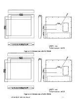
Страница 12: ...APC 3x84B APC 3x85B User Manual 10 Figure 1 3 Dimensions of APC 3784B Figure 1 4 Dimensions of APC 3785B ...
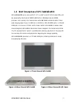
Страница 13: ...APC 3x84B APC 3x85B User Manual 11 Figure 1 5 Dimensions of APC 3984B Figure 1 6 Dimensions of APC 3985B ...
Страница 72: ...APC 3x84B APC 3x85B User Manual 70 Step 3 Read license agreement Click Yes Step 4 Click Next ...
Страница 73: ...APC 3x84B APC 3x85B User Manual 71 Step 5 Click Install Step 6 Click Install ...
Страница 81: ...APC 3x84B APC 3x85B User Manual 79 Step 4 Click Next to continue Step 5 Click Next to continue ...
Страница 84: ...APC 3x84B APC 3x85B User Manual 82 Step 4 Click Finish to complete the installation ...
Страница 88: ...APC 3x84B APC 3x85B User Manual 86 Step 6 Click Continue Anyway Step 7 Click Finish to complete installation ...


