


APC-3X20 User Manual
32
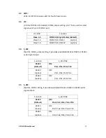
RS485 (option)
Pin#
Signal Name
1
NC
2
NC
3
485-
4
485+
5
Ground
6
NC
7
NC
8
NC
9
NC
BIOS Setup:
Advanced/F81216 Super IO Configuration/Serial Port 0
Configuration
【
RS-485
】
27. JP2:
(2.0mm Pitch 2x3 Pin Header), COM2 jumper setting, pin 1~6 are used to select
signal out of pin 9 of COM2 port.
JP2 Pin#
Function
Close 1-2
COM2 RI (Ring Indicator) (default)
Close 3-4
COM2 Pin9: DC+5V (option)
Close 5-6
COM2 Pin9: DC+12V (option)
28. COM2:
(Type DB9M)
, Rear serial port, standard DB9 Male serial port is provided to
make a direct connection to serial devices.
Pin#
Signal Name
1
DCD# (Data Carrier Detect)
2
RXD (Received Data)
3
TXD (Transmit Data)
4
DTR (Data Terminal Ready)
5
Ground
6
DSR (Data Set Ready)
Содержание APC-3220
Страница 2: ...APC 3X20 User Manual 1 Revision History Reversion Date Description 1 0 2015 10 23 Official Version ...
Страница 12: ...APC 3X20 User Manual 11 1 3 Dimensions Figure 1 1 Dimensions of APC 3220 ...
Страница 13: ...APC 3X20 User Manual 12 Figure 1 2 Dimensions of APC 3920 ...
Страница 14: ...APC 3X20 User Manual 13 Figure 1 3 Dimensions of APC 3420 ...
Страница 16: ...APC 3X20 User Manual 15 Figure 1 6 Front View of APC 3920 Figure 1 7 Rear View of APC 3920 ...
Страница 17: ...APC 3X20 User Manual 16 Figure 1 8 Front View of APC 3420 Figure 1 9 Rear View of APC 3420 ...
Страница 22: ...APC 3X20 User Manual 21 units mm Figure 2 1 Mainboard Dimensions ...
Страница 72: ...APC 3X20 User Manual 71 Step 4 Click Next to continue Step 5 Click Next to continue ...
Страница 75: ...APC 3X20 User Manual 74 Step 4 Click Next to continue Step 5 Click Install to begin the installation ...
Страница 87: ...APC 3X20 User Manual 86 Step 6 Click Continue Anyway Step 7 Click Finish to complete installation ...


