


- 13 -
2018-05-09
Power supply for the Modbus/BACnet module
Voltage:
12-24 V DC
Typical supply current:
50 mA
Maximum power consumption:
2 W
Terminal numbering:
60 and 61 (bipolar connection)
Communication interface
Modbus protocol type:
RTU
BACnet protocol type:
MS/TP (ANSI/ASHRAE standard 135, version 1, revision 9; ISO 16484-5)
Modbus data transmission baud rate:
1200, 2400, 4800, 9600, 19200, 38400, 56000, 57600, 115200
BACnet data transmission baud rate:
9600, 19200, 38400, 57600, 115200
Available data formats:
8E1, 8O1, 8N2
Terminal numbering:
90 (+), 91 (-)
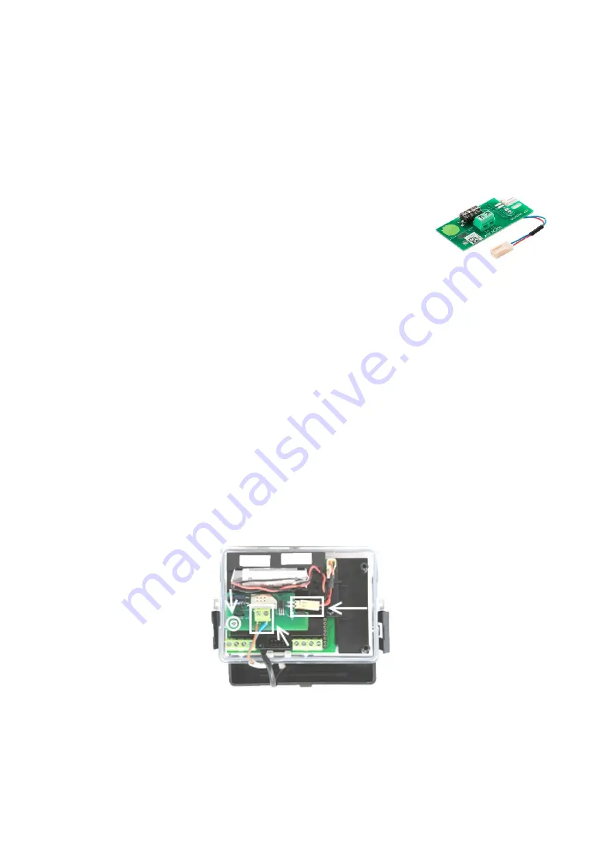
5.2.6. Installation of the external power supply module
Module installation procedure:
1.
Remove the installer's security seals from the calculator enclosure.
2.
Open the calculator's lid by releasing the black latches on the left and right-hand side of the enclosure.
3.
Install the module in place of the second battery holder (see Fig. 5.6.).
4.
Fix the board of the module to the calculator body with one fixing screw supplied with the module
5.
Disconnect the connector plug of the battery installed in the meter from the battery connector and connect it directly to the module (see Fig.
6.
Use a metal tool to short-circuit (for 1-2 seconds) both pins of the battery connector which you have just disconnected from the battery
connector plug. This will unload the internal capacity of the meter bus.
7.
Connect power connector plug of module to the meter's battery connector. The LCD display should start indicating.
8.
By means of pliers remove the protective cap from the spare sealant hole in the bottom part of calculator enclosure.
9.
Insert the power cable (use a flexible two-wired cable 0.14-0.5 mm
2
, with outer diameter 4-6 mm) in sealant hole and route the cable through
an available cable fittings and make a strain relief protecting wire against being pulled out from the outside (see Fig. 10.3.).
10.
Connect wires of the power cable to the screw terminals of external power supply module (bipolar connection). Full terminal assignment of
the external power supply module, see Table 10.3.
11.
Install the configuration pin connector jumper in the test mode (see Fig. 6.7).
12.
Use an optical interface to connect with the optical interface port on the meter's calculator front panel. Press the button on the calculator
front panel and connect with the meter with a dedicated service software suite to set the date and time (Current Readings tab) and disable
the M-Bus data communication limit (Meter Configuration tab).
13.
Remove the configuration pin jumper to disable the test mode and restore the normal operating mode of the heat and cooling meter.
14.
Close the lid of the calculator, secure the side clasps of the calculator enclosure, and install the installer's security seals in place.
15.
Connect the power cable to the external power supply source. The green LED on the calculator front panel should be on – this indicates
that the meter runs on external power.
Fig. 5.6. Installation of external power supply module in the meter’s calculator.
The external power supply module provides possibility of powering meter with 12-42 V DC 12-36 V AC 50/60 Hz,10 mA max. When device is
power supplied from an external source, the meter does not use the internal battery power. The internal battery power in such case is used only
to keep the meter running when the external power supply source is turned off.
The external power supply module can be powered by e.g. the optional 230 V 50/60 Hz / 12 V AC power adapter (see Fig. 5.7.). If you want to
use it, connect the grey cable of the power adapter to the external power supply module terminals by passing it through a cable gland of the
calculator, and connect the black cable marked with label (230 V AC) to the 230 V 50/60Hz power mains. As the power adapter is powered by


