AOpen i915Gm-I Скачать руководство пользователя страница 5


Setting CPU Voltage & Frequency 

Setting CPU Core Voltage 

This motherboard supports Voltage ID (VID) function to detect CPU voltage 
automatically during power-on and the range is from 0.8375V to 1.6V. It’s not 
necessary to set CPU core voltage.   

Setting CPU Frequency


This motherboard is CPU jumper-less design, you can set CPU frequency through 
1MHz stepping CPU Overclocking in the BIOS. CPU Core Frequency = CPU FSB 
clock x CPU Ratio. However, all CPU now selling in the market belong to "Fixed 
Multiplier". That means users can not adjust the CPU Ratio but only change CPU 
FSB clock to achieve overclocking. 


(Users do the overclocking at their own risk!!) 

BIOS Setup > Frequency / Voltage Control > CPU Speed Setup 


CPU Ratio 

8x, 10x… 24x, 25x, 26x, 27x, 28x 

CPU FSB 
(Adjustment manually) 

FSB = 100MHz-400MHz by 1MHz Stepping CPU Overclocking 


Processor Number  Processor Frequency 

FSB 

CPU Ratio 

Cache 

5 Series 

580 

4.00G 

800MHZ 

20x 

1MB L2 

570 

3.80G 

800MHZ 

19x 

1MB L2 

560 

3.60G 

800MHZ 

18x 

1MB L2 

550 

3.40G 

800MHZ 

17x 

1MB L2 

540 

3.20G 

800MHZ 

16x 

1MB L2 

530 

3.00G 

800MHZ 

15x 

1MB L2 

520 

2.80G 

800MHZ 

14x 

1MB L2 

3 Series


350 

3.20G 

533MHZ 

24x 

256K L2 

345 

3.06G 

533MHZ 

23x 

256K L2 

340 

2.93G 

533MHZ 

22x 

256K L2 

335 

2.80G 

533MHZ 

21x 

256K L2 

Note

:

 With CPU speed changing rapidly, there might be faster CPU on the market by the 

time you received this installation guide. This table is kindly for your references only.
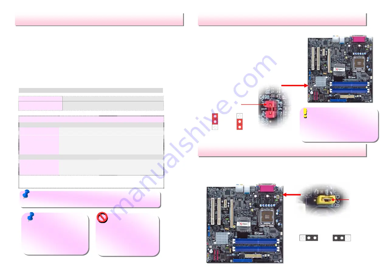


JP14 Clear CMOS 

JP28 Keyboard/Mouse Wakeup Jumper 

This motherboard provides keyboard / mouse wake-up function. You can use JP28 
to enable or disable this function, which could resume your system from suspend 
mode with keyboard or mouse. The factory default setting is “Disable” (1-2), and 
you may enable this function by setting the jumper to 2-3. 

You can clear CMOS to restore system default 
setting. To clear the CMOS, follow the procedure 
below. 
1. Turn off the system and unplug the AC power. 
2. Remove ATX power cable from connector PWR3 
3. Locate JP14 and short pins 2-3 for a few seconds. 
4. Return JP14 to its normal setting by shorting pin 

1 & pin 2. 

5. Connect ATX power cable back to connector 

PWR3. 

Pin 1 

Pin 1 

Note: Some CPU fans do not have sensor pin so they cannot 

support fan monitoring. 

Warning: Intel 915G 

chipset support maximum 
800MHz (200MHz*4) system 
bus; higher clock setting may 
cause serious system 
damage.


Tip: When should I Clear CMOS? 

1. Boot fails because of overclocking… 
2. Forget password… 
3. Troubleshooting… 

1

Disable 

(Default) 

1


Enable 

Note:  Intel 915G chipset 

support Prescott processor. 
Prescott processor could detect 
the clock ratio automatically; 
you may not be able to adjust 
the clock ratio in BIOS manual. 

Normal  

(default) 

Clear CMOS 

Содержание i915Gm-I

Страница 1: ...nnector AOpen reserves the right to revise all the specifications and information contained in this document which are subject to change without notice COM2 Connector Front Audio Connector USB 2 0 Connector Front Panel Connector Case Open Connector Serial ATA Ports x4 Supports 150 MB s Transfer Rate FDD Connector SYSFAN1 Connector Front USB 2 0 Connector 4 pin 12V ATX Power Connector Intel Gigabit...

Страница 2: ...d in the Bonus Pack CD Thanks for the help of saving our earth 1 Installing CPU 2 Installing CPU Fan System Fan 3 Installing Memory Module 4 Installing HD CD ROM and SATA Disk etc 6 Connecting ATX Power Cable 5 Connecting Front Panel Cable 7 Installing PCI Express x16 Graphics cards PCI Express x 1 cards PCI Cards 8 Installing Other Devices USB Front Audio etc 9 Connecting Back Panel Ports Keyboar...

Страница 3: ... very easy to recognize Insert the module straight down to the DIMM slot with both hands and press down firmly until the DIMM module is securely in place 4 Connecting IDE and Floppy Cables Connect 34 pin floppy cable and 40 pin 80 wire IDE cable to floppy connector FDD and IDE connector Be careful of the pin1 orientation Wrong orientation may cause system damage Pin 1 ATA 66 100 IDE Connector FDD ...

Страница 4: ...ting Front Panel Cable 6 Connecting ATX Power Cable This motherboard comes with a 24 pin ATX power connector and a 4 pin 12V ATX power connector as shown below Make sure you plug in the right direction We strongly recommend you to insert the 4 pin connector before connecting the 24 pin connector 7 Power on and Loading BIOS Setup Del 8 AOpen Bonus Pack CD and EzInstall You can use the autorun menu ...

Страница 5: ... With CPU speed changing rapidly there might be faster CPU on the market by the time you received this installation guide This table is kindly for your references only JP14 Clear CMOS JP28 Keyboard Mouse Wakeup Jumper This motherboard provides keyboard mouse wake up function You can use JP28 to enable or disable this function which could resume your system from suspend mode with keyboard or mouse ...

Страница 6: ...e front audio panel of the housing should be designed for High definition Audio jack If the front audio panel is not designed for High Definition Audio jack we strongly recommend you to connect the microphone to the back panel of the motherboard IrDA Connector The IrDA connector can be configured to support wireless infrared module with this module and application software such as Laplink or Windo...

Страница 7: ...corner of first boot screen POST screen For example i915Gm IE is model name of motherboard R1 02 is BIOS version Register Your Motherboard Thanks for choosing AOpen product please register this motherboard at http club aopen com tw productreg to become a Gold member of Club AOpen and to ensure high service quality and priority from AOpen You will also have a chance to play slot machine game to win...

Страница 8: ...ks very much for your understanding Europe Email Support AOpen NL Pacific Rim http www aopen com tw tech default htm China http www aopen com cn tech default htm Germany http www aopencom de tech default htm America http usa aopen com tech default htm Japan http aopen jp tech index html Europe AOpen Computer b v Tel 31 73 645 9516 Email Support AOpen NL China 艾爾鵬國際貿易 上海 有限 公司 Tel 86 21 6225 8622 F...

Отзывы: