


Pin 1
Primary
Master (1st)
Primary
Slave (2nd)
This socket supports uFCPGA & uFCBGA package CPU, which is the latest CPU
package developed by Intel. Other forms of CPU package are impossible to be
fitted in.
1.
Unscrew socket screw counter-
clockwise.
2.
Locate Pin 1 in the socket and
look for a golden arrow on the
CPU upper interface. Match Pin 1
and golden arrow. Then insert
the CPU into the socket.
3.
Lock the socket screw clockwise
to fasten CPU.
3. Installing Memory Modules
2. Installing CPU & System Fans
1. Installing CPU
Plug in the CPU fan cable to the 4-pin CPUFAN connector. If you have chassis fan,
you can also plug it in SYSFAN1 or SYSFAN2 connector.
SYSFAN1 Connector
CPUFAN Connector
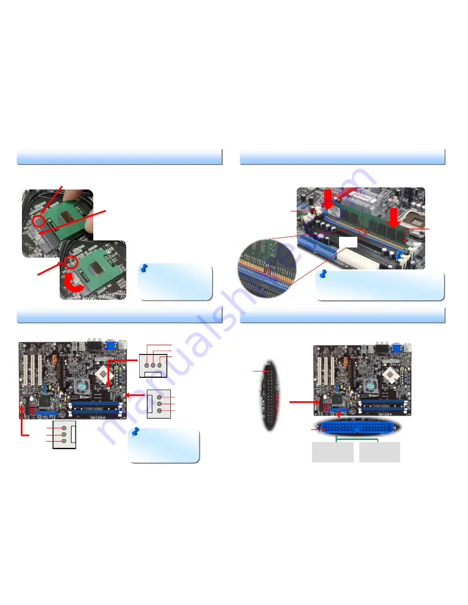
4. Connecting IDE and Floppy Cables
Connect 34-pin floppy cable and 40-pin, 80-wire IDE cable to floppy connector FDD
and IDE connector. Be careful of the pin1 orientation. Wrong orientation may cause
system damage.
FDD Connector
Note:
Some CPU fans
do not have sensor pin so
they cannot support fan
monitoring.
+12V
Sensor
GND
Tab
Pin 1
GND
+12V
Sensor
SYSFAN2 Connector
Pin 1
ATA 66/100 IDE
Connector
DIMM slots are designed in black and navy blue which are very easy to recognize.
Insert the module straight down to the DIMM slot with both hands and press down
firmly until the DIMM module is securely in place.
Note:
The tabs of the DIMM slot will close-up to
hold the DIMM in place when the DIMM touches the
slot’s bottom.
Socket Pin 1
Golden arrow
Note:
If you do not
match the CPU socket Pin 1
and CPU golden arrow well,
you may damage the CPU.
Socket Screw
+12V
Sensor
GND
Key


