AOpen DX34 Plus Скачать руководство пользователя страница 3

This motherboard supports DUAL processors for Intel PentiumII / Pentium!!!, and 
Celeron CPU (applied to PPGA package only, must lower than 300MHz). Please refer 
to the following table for detail. It is not  recommended to change the default setting, 
unless the system fails to boot and you’re trying to troubleshoot. 


Processor  CPU Package 

Configuration 

Single Processor 

PentiumII 

Pentium!!! 

Celeron 

All 

Default 

PentiumII 

Pentium!!! 

All 

Default 

Celeron 

PPGA 

Set the SW3 to OFF 

Dual Processor 

Celeron 

FC-PGA 

Not Supported 

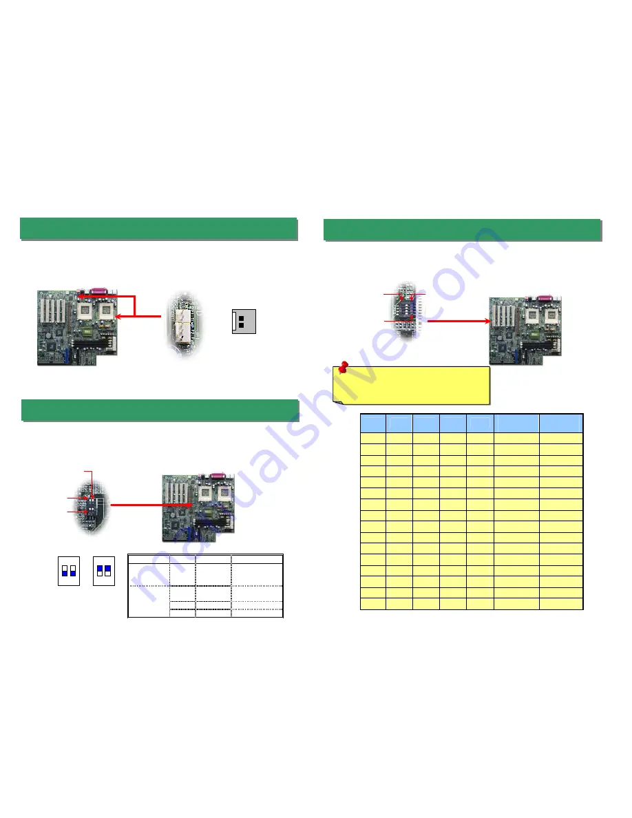
When you are using the Intel

®  

engineer sample CPU with DX34/DX34Plus, the SW1 

allows you select the CPU ratio from 2x to 9.5 x. You can adjust the SW1 to get the correct 
CPU working ratio and frequency.  

5. SW1 Setting CPU FSB Frequency & Ratio 

4. SW3 Select CPU Type 

3. Installing Thermal Sensor 

GND 

Sensor


The Thermal Sensor Connector (CN12 & CN1) provides you to use the thermal sensor 
to detect the CPU temperature of the components on the motherboard.


OFF 

ON

1

SW3 

Warning:

 We strongly recommend you do 

not overclocking your CPU and system for 
get more system reliability.


SW1


ON 

OFF 

Bit1 

Bit2 

Bit3 

Bit4 

Ratio 

Frequency 

(FSB100) 

Frequency 

(FSB133) 

On 

On 

On 

On 

X2 

200 

266 

On 

Off 

On 

On 

X2.5 

250 

333 

On 

On 

Off 

On 

X3 

300 

400 

On 

Off 

Off 

On 

X3.5 

350 

466 

On 

On 

On 

Off 

X4 

400 

533 

On 

Off 

On 

Off 

X4.5 

450 

600 

On 

On 

Off 

Off 

X5 

500 

667 

On 

Off 

Off 

Off 

X5.5 

550 

733 

Off 

On 

On 

On 

X6 

600 

800 

Off 

Off 

On 

On 

X6.5 

650 

866 

Off 

On 

Off 

On 

X7 

700 

933 

Off 

Off 

Off 

On 

X7.5 

750 

1000 

Off 

On 

On 

Off 

X8 

800 

1066 

Off 

Off 

On 

Off 

X8.5 

850 

1133 

Off 

On 

Off 

Off 

X9 

900 

1200 

Off 

Off 

Off 

Off 

X9.5 

950 

1266 


1


2


ON


(Default) 

1


2


ON


Содержание DX34 Plus

Страница 1: ...In DX34 Only FAX VOICE DX34 Only AC97 CODEC C hip DX34 Only Intel 82559 10 100 LAN Controller AGP Pro Slot 32 Bit PCI Slot x 5 4Mbit Flash BIOS SCSI HDD LED Connector Adaptec Ultra3 S CSI Controller D...

Страница 2: ...n the CPU fan cable to the CPU FAN connector and housing fan cable to the Housing Fan connector For DX34 Plus we provide two configurations of system fan connector for better compatibility with differ...

Страница 3: ...frequency 5 SW1 Setting CPU FSB Frequency Ratio 4 SW3 Select CPU Type 3 Installing Thermal Sensor GND Sensor The Thermal Sensor Connector CN12 CN1 provides you to use the thermal sensor to detect the...

Страница 4: ...34 pin floppy cable and 40 pin ATA66 or ATA33 IDE cable to floppy connector FDC and IDE connector IDE1 IDE2 Pin1 of cable is normally marked with red color Be careful of the pin1 orientation Wrong or...

Страница 5: ...ector Read or write activity by devices connected to the SCSI card will cause the LED lighting up If you have installed the CD ROM drive in the system the CD In Connector CN19 can be connected to audi...

Страница 6: ...ator Control DX34 Plus only 17 Installing Onboard Sound Driver 16 Power On and Load BIOS Setup After you finish the setting of jumpers and connect correct cables Power on and enter the BIOS Setup pres...

Страница 7: ...fective No Yes No Yes It is very possible that your keyboard is defective During system rebooting press Del to enter BIOS Setup Choose Load Setup Default The problem should be caused by the IDE cables...

Страница 8: ...ably had been answered by our support engineer or professional users on the news group http www aopen com tech newsgrp default htm 4 4 Contact Distributors Resellers We sell our products through resel...

Отзывы: