


Connector
Pin1
Pin2
Pin3
Pin4
AUX-IN
Left
GND GND
Right
CD-IN
Left
GND GND
Right
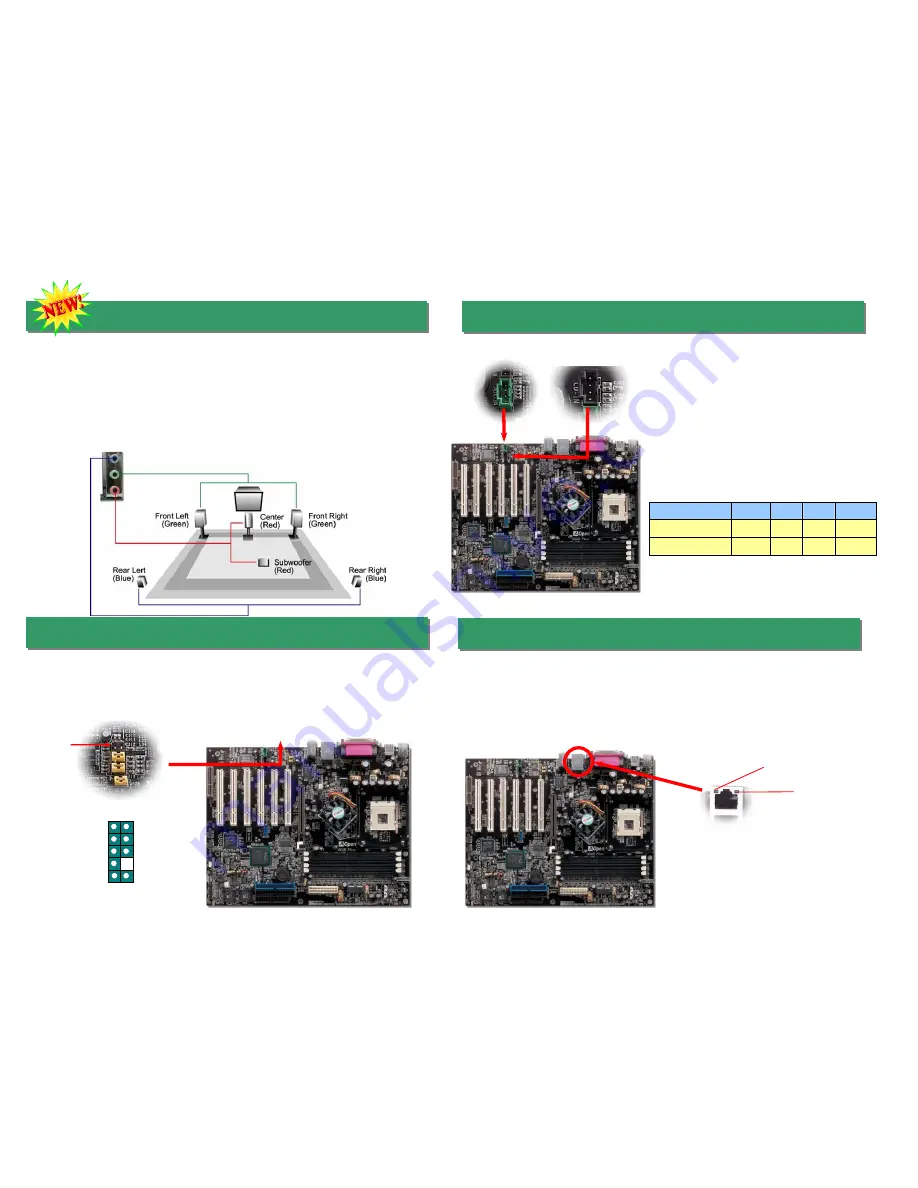
10. Super 5.1 Channel Audio Effects
This motherboard comes with an ALC650 CODEC, which supports high quality of 5.1
Channel audio effect, bringing you a brand new audio experience. On the strength of the
innovative design of ALC650, you're able to use standard line-jacks for surround audio
output without connecting any external module. To apply this function, you have to install
the audio driver in the Bonus Pack CD as well as an audio application supporting 5.1
Channel. Picture bellow represents the standard location of all speakers in 5.1 Channel
sound track. Please connect the plug of your front speakers to the green “Speaker out”
port, rear speakers’ plug to the blue “Line in” port and both of the center and subwoofer
speakers to the red “MIC in” port.
12. Connecting CD-IN /AUX-IN Connector
11. Front Audio Connector
If the housing has been designed with an audio port on the front panel, you’ll be able to
connect onboard audio to front panel through this connector. By the way, please remove
5-6 and 9-10 jumper caps from the Front Audio Connector before connecting the cable.
Please do not remove these 5-6 and 9-10 yellow jumper caps if there’s no audio port on
the front panel.
Pin 1
AUD_MIC
AUD_MIC_BIAS
AUD_FPOUT_R
NC
AUD_FROUT_L
AUD_GND
AUD_VCC
AUD_RET_R
KEY
AUD_RET_L
9 10
1 2
The
AUX-IN
connector is used to connect MPEG
Audio cable from MPEG card to onboard sound.
The
CD-IN
connector is used to connect CD
Audio cable from CDROM or DVD drive to
onboard sound.
CD-IN (Black)
AUX-IN (Green)
13. Support 10/100 Mbps LAN onboard
On the strength of RealTek RTL8100BL LAN controller on board, which is a
highly-integrated Platform LAN Connect device, it provides 10/100M bps Ethernet for office
and home use, the Ethernet RJ45 connector is located on top of USB connectors. The
green LED indicates the link mode, it lights when linking to network and blinking when
transferring data. The orange LED indicates the link mode, it lights when linking to network.
The green LED indicates the transfer mode, and it lights when data is transferring. To
enable or disable this function, you may simply adjust it through BIOS.
Green/Transfer
Orange/Link


