AOpen AK77-600N Скачать руководство пользователя страница 4


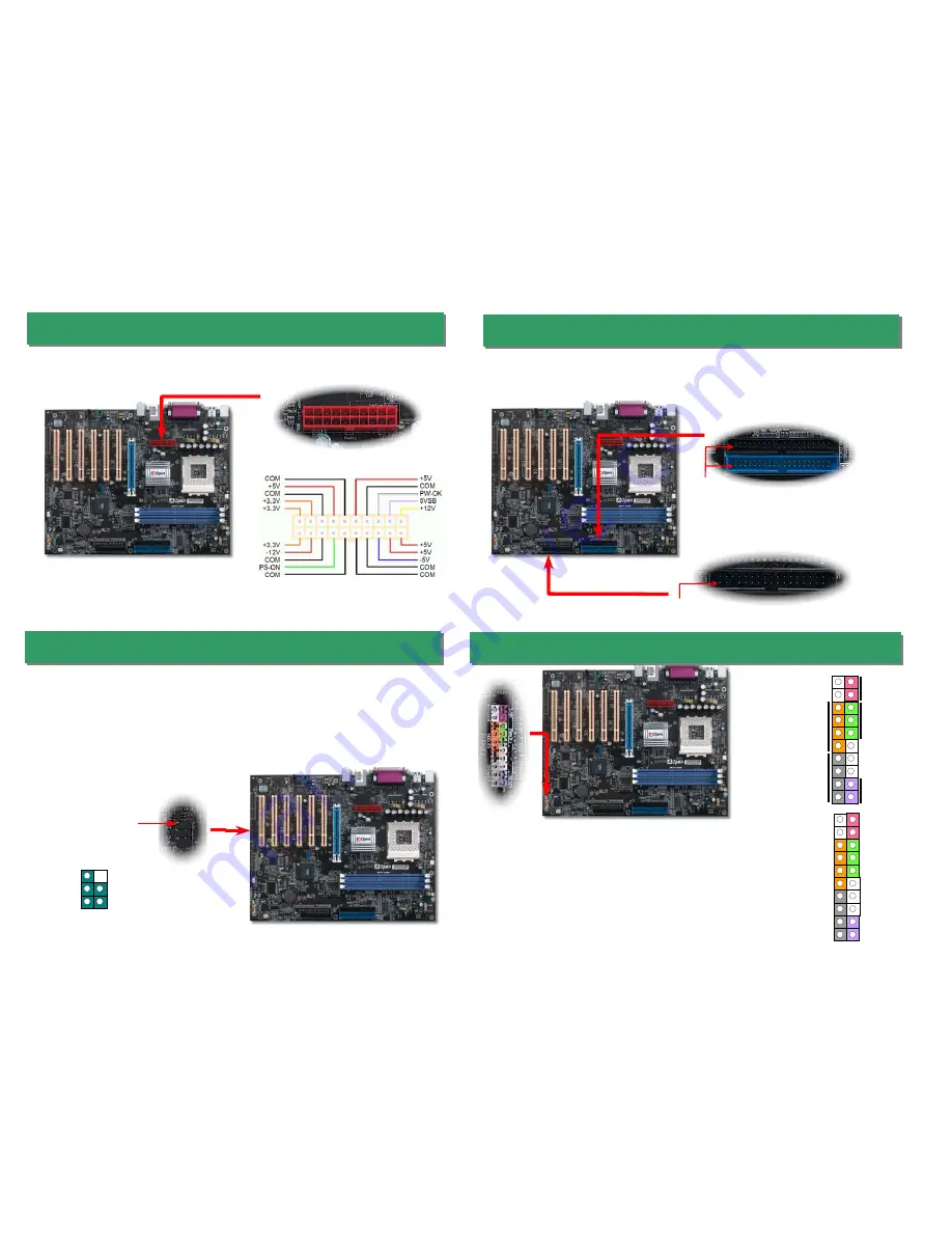
9. Connecting Front Panel Cable 

Attach the power LED, speaker, and reset switch connectors
to the corresponding pins. If you enable “Suspend Mode”
item in BIOS Setup, the ACPI & Power LED will keep
flashing while the system is in suspend mode.


Locate the power switch cable from your ATX housing. It is 
2-pin female connector from the housing front panel. Plug 
this connector to the soft-power switch connector marked 

SPWR

.


8. Connecting IDE, Floppy Cables 

Pin 1

ATA 66/100/133 

IDE Connector

FDD Connector 

Connect 34-pin floppy cable and 40-pin IDE cable to floppy connector FDD connector. Be
careful of the pin1 orientation. Wrong orientation may cause system damage.


IDE 2 (Secondary)   

IDE 1 (Primary) 

Pin 1

6. Connecting ATX Power Connector 

The ATX power supply uses a 20-pin connector shown below. Make sure you plug in the
right direction.   

7. Connecting IrDA Connector 

The IrDA connector can be configured to support wireless infrared module, with this module
and application software such as Laplink or Windows 95 Direct Cable Connection, the user
can transfer files to or from laptops, notebooks, PDA devices and printers. This connector
supports HPSIR (115.2Kbps, 2 meters) and ASK-IR (56Kbps).   

Install the infrared module onto the 

IrDA 

connector and enable the infrared function from

BIOS Setup, UART mode select, make sure to have the correct orientation when you plug
in the IrDA connector. 

ATA 66/100/133 

KEY 

GND 

IR_RX 

NC

+5V

IR_TX

IrDA Connector 

Pin 1 

SPEAKER

IDE LED

Power Switch 

ACPI & Power LED 

RESET 

SPWR 

GND 

ACPILED- 

GND 


NC 

NC 

GND 

RESET 

GND 

NC

NC

+5V

IDE LED

IDE LED

+5V

+5V

GND

NC

SPEAKER

Содержание AK77-600N

Страница 1: ...nal WOM Wake ON Modem Connector WOL Wake ON LAN Connector IrDA Connector SYSFAN2 Connector Front Audio Connector Front Panel Connector JP14 CMOS Data Clear Jumper Case Open Connector JP20 K7 Host Clock Select Jumper USB2 0 Connector S PDIF Connector RealTek RTL8100BL 2200μF Low ESR Capacitors JP28 Keyboard Mouse Wakeup Jumper PS 2 Mouse Connector PS 2 Keyboard Connector USB2 0 Ports SPP EPP ECP Pa...

Страница 2: ... unplug the AC power 2 Remove ATX power cable from connector PWR2 3 Locate JP14 and short pins 2 3 for a few seconds 4 Return JP14 to its normal setting by shorting pin 1 pin 2 5 Connect ATX power cable back to connector PWR2 Tip When should I Clear CMOS 1 Boot fail because of overclocking 2 Forget password 3 Troubleshooting Pin 1 Normal Operation default Clear CMOS 1 1 2 JP28 Keyboard Mouse Wake ...

Страница 3: ...justment technology FSB 200 200 250 by 1MHz stepping adjustment technology CPU CPU Core Frequency EV6 Bus Clock Ratio Athlon 1 33G 1 33GHz 266MHz 10 0x Athlon 1 4G 1 4GHz 266MHz 10 5x AthlonXP 1500 1 3GHz 266MHz 10 0x AthlonXP 1600 1 4GHz 266MHz 10 5x AthlonXP 1700 1 46GHz 266MHz 11 0x AthlonXP 1800 1 53GHz 266MHz 11 5x AthlonXP 1900 1 6GHz 266MHz 12 0x AthlonXP 2000 1 667GHz 266MHz 12 5x AthlonXP...

Страница 4: ... 6 Connecting ATX Power Connector The ATX power supply uses a 20 pin connector shown below Make sure you plug in the right direction 7 Connecting IrDA Connector The IrDA connector can be configured to support wireless infrared module with this module and application software such as Laplink or Windows 95 Direct Cable Connection the user can transfer files to or from laptops notebooks PDA devices a...

Страница 5: ...ting 5 1 Channel Picture bellow represents the standard location of all speakers in 5 1 Channels sound track Please connect the plug of your front speakers to the green Speaker out port rear speakers plug to the blue Line in port and both of the center and subwoofer speakers to the red MIC in port 12 S PDIF Connector S PDIF Sony Philips Digital Interface is a newest audio transfer file format whic...

Страница 6: ...ent You may accomplish BIOS upgrade procedure with EzWinFlash by the following steps and it s STRONGLY RECOMMENDED to close all the applications before you start the upgrading 1 Download the new version of BIOS package zip file from AOpen official web site ex http english aopen com tw 2 Unzip the download BIOS package ex WAK77600N102 ZIP with WinZip http www winzip com in Windows environment 3 Sav...

Страница 7: ...d correctly For P4 system please also plug the 4pin 12V cord Install the VGA card Then connect your monitor and keyboard The problem was probably caused by power supply or motherboard failure Please contact your reseller or local distributor for repairing Perhaps your VGA card or monitor is defective No Yes No Yes It is very possible that your keyboard is defective During system rebooting press De...

Страница 8: ...e directory choose Manuals to go to our manual database You can also find the manual and EIG in AOpen Bonus Pack http download aopen com tw downloads 1 1 Test Report We recommend you to choose board card device from the compatibility test reports for assembling your PC It may prevent incompatibility problems http english aopen com tw tech report default htm 2 2 FAQ Here we list problems that users...

Отзывы: