background image

Doc.Id. SCM-1200-093

Anybus Communicator for Modbus Plus
Doc.Rev. 3.01

Chapter 7

7. Frame Objects

7.1 General

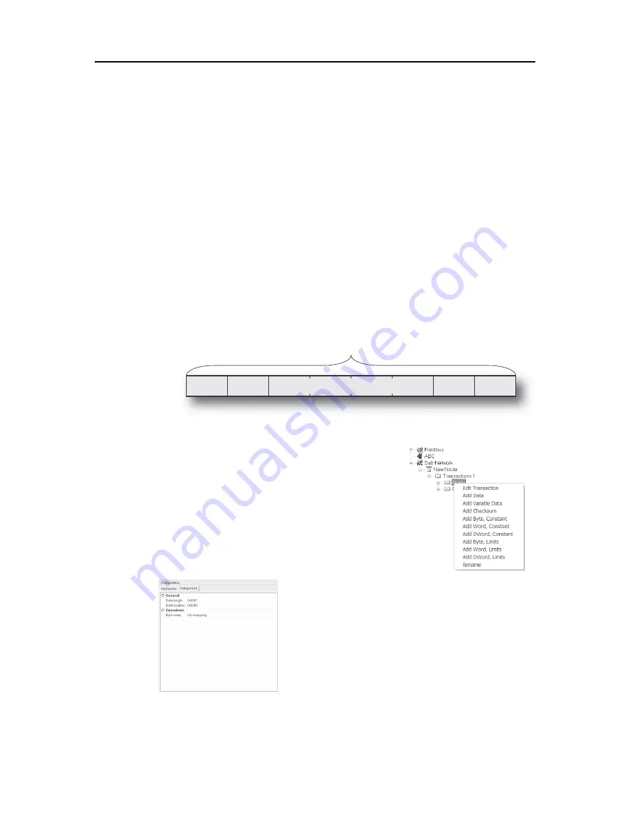
Each transaction consists of Frame Objects which makes up the serial telegram frame. Each Frame Ob-
ject specifies how the gateway shall interpret or generate a particular part of the telegram.

There are 5 types of frame objects, which are described in detail later in this chapter:

• Constant Objects
• Limit Objects
• Data  Objects
• Variable Data Objects
• Checksum Objects

Example:

The following Transaction consists of several frame objects; three constants, a data object, and 
a checksum object.

7.2 Adding and Editing Frame Objects

To add a frame object to a Transaction, right-click on the Transac-
tion in the Navigation Section and select one of the entries in the 
menu that appears.

The entry called ‘Transaction Editor’ will launch the Transaction 
Editor, which is used to edit transactions and frame objects in a 
more visual manner. For more information, see  “Transaction Edi-
tor” on page 38.

To edit parameters associated with a particular frame object, select 
the frame object in the Navigation Section. The settings for that 
frame object will be displayed in the Parameter Section.

It is also possible to edit the frame objects in a transaction in a 
more visual manner using the Transaction Editor, see  “Transac-
tion Editor” on page 38

Transaction

Constant

Constant

Variable Length Data

Checksum

Constant

Data Object, Parameters

Содержание Communicator Modbus plus

Страница 1: ...trial Networks Mailing address Box 4126 300 04 Halmstad Sweden Visiting address Stationsgatan 37 Halmstad Sweden Connecting DevicesTM E mail info hms networks com Web www anybus com User Manual Anybus...

Страница 2: ...that may arise as a result from the use of undocumented features timing or functional side effects found outside the documented scope of this product The effects caused by any direct or indirect use...

Страница 3: ...ion Manager 13 Chapter 2 Basic Operation General 14 Data Exchange Model 15 Memory Map 15 Data Exchange Example 16 Subnetwork Protocol 17 Protocol Modes 17 Protocol Building Blocks 17 Master Mode 18 Ge...

Страница 4: ...Broadcast 34 Parameters Response 36 Transaction Parameters Generic Data Mode 36 Produce Transactions 36 Consume Transactions 37 Transaction Editor 38 Chapter 7 Frame Objects General 39 Adding and Edit...

Страница 5: ...ns 62 Chapter 12 Data Logger General 63 Operation 63 Configuration 64 Chapter 13 Configuration Wizards General 65 Selecting a Wizard Profile 65 Wizard Modbus RTU Master 66 Chapter 14 Control and Statu...

Страница 6: ...tor 74 Subnetwork Interface 75 General Information 75 Bias Resistors RS485 Only 75 Termination RS485 RS422 Only 75 Connector Pinout DB9F 75 Typical Connection RS485 76 Typical Connection RS422 4 Wire...

Страница 7: ...e transactions 32 Updated information about the trigger byte 37 Updated information about the CRC algorithm 44 Updated frontpage information Updated sales and support page Updated System Requirements...

Страница 8: ...ng ABC Anybus Communicator Broadcaster A protocol specific node in the configuration that handles transactions destined to all nodes MBP Modbus Plus Command A predefined transaction Configuration List...

Страница 9: ...a E mail cn sales hms networks com E mail cn support hms networks com Phone 86 0 10 8532 3183 Phone 86 0 10 8532 3023 Fax 86 0 10 8532 3209 Fax 86 0 10 8532 3209 Online www anybus cn Online www anybus...

Страница 10: ...TER INVERTER INVERTER INVERTER INVERTER INVERTER INVERTER INVERTER INVERTER INVERTER INVERTER INVERTER INVERTER INVERTER INVERTER INVERTER INVERTER INVERTER INVERTER INVERTER INVERTER INVERTER INVERTE...

Страница 11: ...or is used to connect the gateway to a PC for configuration and monitoring purposes See also Hardware Installation on page 12 PC Connector on page 74 E Sub network Connector This connector is used to...

Страница 12: ...a timeout occurs on a transaction this led will turn red Off Power off Green flashing Running correctly but one or more transaction error s have occurred Green Running Red Transaction error timeout o...

Страница 13: ...er to have effect Normally these switches are covered by a plastic hatch When removing the hatch avoid touching the circuit boards and components inside The switches are interpreted as follows Switch...

Страница 14: ...n 2 To snap the gateway off push it downwards 1 and pull it out from the DIN rail 2 as to make it snap off from the DIN rail 2 Connect the gateway to the Modbus Plus network 3 Set the Modbus Plus Node...

Страница 15: ...resolution of 800x600 16 bit color or higher Microsoft Windows 2000 XP Vista 7 32 bit Internet Explorer 4 01 SP1 or newer Installation Anybus Communicator resource CD Insert the CD and follow the ons...

Страница 16: ...elegrams cyclically on change of state or based on trigger events issued by the control system of the higher level network i e the fieldbus master or PLC It can also monitor cer tain aspects of the su...

Страница 17: ...is area can be written to by the higher level network how this data is represented on the higher level network will be described later in this chapter General Data This area cannot be accessed from th...

Страница 18: ...utput Register of the Temperature Regulator to the Input Data area The gateway copies the Temperature Setpoint from the Output Data area to the Input Register in the Temperature Regulator The PLC Memo...

Страница 19: ...p between the subnetwork nodes and the gate way any node on the subnetwork including the gateway may spontaneously produce or con sume messages For more information about this mode see Generic Data Mo...

Страница 20: ...st protocols offer some way of broadcasting mes sages to all nodes on the network without expecting them to respond to the broadcasted message This is also reflected in the gateway which features a de...

Страница 21: ...have to respond to messages nor do they have to wait for a query in order to send one In the figure above the gateway consumes data that is produced by a node on the subnetwork This consumed data can...

Страница 22: ...ed automatically with another node each token pass The node ID of that node is determined by the Source ID switches see Configuration Switches on page 11 The gateway can exchange up to 32 words of glo...

Страница 23: ...odbus registers as follows 2 4 6 Point to Point Exception Handling When the gateway receives a query which for some reason cannot be processed i e when trying to ac cess a non existent register an exc...

Страница 24: ...ccess to these parame ters the entry must be expanded by clicking There are three main levels in the navigation window namely Fieldbus ABC and subnetwork Right clicking on entries in this section brin...

Страница 25: ...tion Save As Save the current configuration under a new name Print Send details about the current configuration to a printer Properties This brings out the following window CAUTION Always keep a copy...

Страница 26: ...A confirmation dialog is displayed when closing the Anybus Configuration Man ager with unsaved data Show Wizard when New menu is selected The Wizard is displayed each time a new configuration is creat...

Страница 27: ...ables disables the status bar at the bottom of the main window Help This menu features the following entries Contents Display the table of contents of the online help system Note At the time of writin...

Страница 28: ...guration Manager to disconnect from the gateway Start Logging Stop Logging See Tools on page 24 Data Logger on page 63 Subnetwork Monitor Clicking on this icon will launch the subnetwork Monitor see S...

Страница 29: ...ports a wide range of net working systems Make sure that this parameter is set to Modbus Plus IO Sizes These parameters specify how data from the internal memory buffer shall be exchanged on Modbus Pl...

Страница 30: ...tting is similar to Enabled except that the control system is not required to set the Data Valid bit to start the subnetwork communication Disabled This setting completely disables the Control and Sta...

Страница 31: ...ssfully been ex changed on the subnetwork This feature is primarily intended for debugging purposes Receive Counter Location Specifies the location of the Receive Counter in the internal memory buffer...

Страница 32: ...messages in steps of 10ms If set to 0 zero the gateway will use the standard Modbus delimiter of 3 5 characters the actual number of ms will be calculated automatically based on the currently used com...

Страница 33: ...in access to these functions 5 3 Node Parameters 5 3 1 Master Mode and Generic Data Mode To gain access to the parameters described in this section select a node in the Navigation Section Function Des...

Страница 34: ...ree protocol modes Master Mode For regular nodes transactions always come in pairs a query and a response The query is issued by the gateway while responses are issued by the slaves on the subnetwork...

Страница 35: ...Master Mode On regular nodes this adds a Query and a Response The two transactions will be grouped in order to increase readability On the Broadcaster a single transaction will be added Add Transacti...

Страница 36: ...reconnect a dis connected node A node will be disconnected in case the maximum number of retries below has been reached The entered value is multiplied by 10 For instance an entered value of 5 result...

Страница 37: ...Rev 3 01 Update time 10 ms This parameter specifies how often the transaction will be issued in steps of 10 ms only rele vant when Update mode is set to Cyclically The entered value is multiplied by 1...

Страница 38: ...is sent to the subnetwork Clear Data is cleared 0 on the subnetwork if the higher level network goes offline Freeze Data is frozen on the subnetwork if the higher level network goes offline NoScanning...

Страница 39: ...data that is sent to the higher level network Clear Data is cleared 0 on the higher level network if the subnetwork goes offline Freeze Data is frozen on the higher level network if the subnetwork goe...

Страница 40: ...e transaction may not be ed itable The File menu features the following entries Example The transaction created in this example are built up as follows The first byte holds the STX 0x02 followed by tw...

Страница 41: ...ting Frame Objects To add a frame object to a Transaction right click on the Transac tion in the Navigation Section and select one of the entries in the menu that appears The entry called Transaction...

Страница 42: ...ly depending on the direction of the transaction Produce Query Transactions The gateway will send the value as it is without processing it Consume Response Transactions The gateway will check if the r...

Страница 43: ...ide the specified boundaries If not the message will be discarded There are 3 types of interval objects Byte 8 bit interval Word 16 bit interval Dword 32 bit interval To set the range of the object se...

Страница 44: ...system must supply an End or Length character in order for the gateway to know the size of the data block The End or Length character itself may either be forwarded to the subnetwork or discarded Con...

Страница 45: ...ritten to Object Delimiter Length Character Length character is visible in the internal memory buffer but not on the subnetwork Length Character Visible The length character is visible both in the int...

Страница 46: ...is parameter specifies which type of algorithm to use CRC 2 bytes CRC 16 with 0xA001 polynome Modbus RTU standard LRC 1 byte All bytes are added together as unsigned 8 bit values The 2 s complement of...

Страница 47: ...see Node Parameters on page 31 In such case the parameters in the parameter section will be greyed out and cannot be edited directly In Master Mode Anybus Configuration Manager comes preloaded with co...

Страница 48: ...the Command Editor See also The Command Editor on page 47 Edit Command Edit the currently selected command using the Command Editor See also The Command Editor on page 47 Delete Command Delete the cu...

Страница 49: ...ocol 8 3 2 Basic Navigation Open the Command Editor by selecting Edit Command or Add Command from the Command menu A Pull down Menu See Pull down Menu on page 48 B Name of Command Actual name of the c...

Страница 50: ...following entries Apply Changes Save changes and exit to the main window Exit Exit without saving Column The functions in this menu alters the structure of the command Append Column Add another column...

Страница 51: ...ly manner when editing its settings in the Transaction Editor or in the Parameter Section of the Main Window ObjectType This row specifies the type of frame object that shall be used for the column Va...

Страница 52: ...d to be broadcasted check the Allow Broadcasting checkbox Query 1 2 3 4 DisplayName Slave Address Function Data Checksum Object Type Byte Object Byte Object Data Object Checksum Object Value SlaveAddr...

Страница 53: ...k The communication is based on a query response scheme where the gateway issues a query on the sub network The addressed node on the subnetwork is expected to issue a response to that query Nodes are...

Страница 54: ...unter in the internal memory buffer Transmit Counter Location Specifies the location of the Transmit Counter in the internal memory buffer Both counters are enabled by setting Statistics to Enabled Va...

Страница 55: ...5 Start bits Number of start bits Stop bits Number of stop bits 1 Parameter Description Master Node Address Node address of the master valid values 0 254 default 1 Poll time active slaves 10 ms Determ...

Страница 56: ...ch slave with services that can be issued from the master A total of 50 services are allowed The Anybus Communicator supports a selection of DF1 commands When the gateway is going to ex ecute a servic...

Страница 57: ...es offline This option affects the data that is reported to the fieldbus master Clear Freeze Update mode The update mode for this service Cyclically On data change Single shot Change of state on trigg...

Страница 58: ...read The size is given in bytes which means that it always has to be an even number as only whole elements can be read from the slave One bit integer element is 2 bytes and one float element is 4 byte...

Страница 59: ...e file number of the data file to be accessed PLC 5 3 7 8 10 999 SLC500 3 7 8 10 255 MicroLogix 3 7 8 10 255 File type The file type of the data to be accessed Integer Bit Float Size The number of byt...

Страница 60: ...should be used with care Operation A Start Network Stop Network Icons These icons controls the subnetwork activity To stop all subnetwork activity click on the red light To start the subnetwork again...

Страница 61: ...a negative influence on the overall performance of the gateway i e it should be used only when necessary The Node Monitor behaves somewhat differently in the three protocol modes Master Mode and DF1 M...

Страница 62: ...a similar way as in the Transaction and Command Editors C Response Section Master Mode and DF1 Master Mode only This section holds the response to the selected Command D Monitor Section This section d...

Страница 63: ...node Start Node Enable the transactions associated with the node Stop Node Disable the transactions associated with the node Command This menu is used to specify and issue a command manually Select Co...

Страница 64: ...Select Command Send Command These icons corresponds to the functions in the Command menu See also Command on page 61 Resume Refresh Stop Refresh When enabled the data displayed in the Monitor Section...

Страница 65: ...g Select Start Logging in the Tools menu Anybus Configuration Manager will then prompt for the desired mode of operation see below Stop logging Select Stop Logging in the Tools menu This will open the...

Страница 66: ...d 512 bytes of data in each direction To specify a different size for the buffer select Options in the Tools menu A window with various settings will appear Select the ABC tab and enter the desired nu...

Страница 67: ...wizard profile in all other cases the Blank Configuration option must be used 13 2 Selecting a Wizard Profile The following window appears each time the Anybus Configuration Manager is started or upo...

Страница 68: ...serial communication requirements and if necessary contact the manufacturer of the device to obtain further informa tion about the serial communication protocol In the event that the wizard doesn t h...

Страница 69: ...he sub network If enabled these registers occupy the first two bytes in the input and output data areas 0x000 0x001 and 0x200 0x201 respectively which means they can be accessed from the fieldbus just...

Страница 70: ...ldbus control system and the gateway are online on the field bus network and shift to state B B Online Not yet exchanging data 4 Wait until the Data Valid bit in the Status Register is cleared by the...

Страница 71: ...See also Handshaking Procedure on page 67 Control Register Contents Control System to Gateway on page 71 14 Confirm SR_HS_CONFIRM 13 Data Valid Master Mode and DF1 Master Mode Only This bit is set wh...

Страница 72: ...ter Updated Error Counter The number of invalid transactions i e received transac tions which doesn t match any of the consume transactions defined in the subnetwork configuration has increased 0x01 F...

Страница 73: ...ge 67 Status Register Contents Gateway to Control System on page 69 14 Send CR_HS_SEND 13 Data Valid This bit controls data consistency see Data Consistency on page 68 1 Output Area valid exchange dat...

Страница 74: ...e in the Mailbox Editor see below A mailbox message is a HMS specific command structure used for low level communication with an Anybus S interface Consult the Anybus S Parallel Design Guide and the f...

Страница 75: ...A 2 Power Connector Notes Use 60 75 or 75 C copper CU wire only The terminal tightening torque must be between 5 7 lbs in 0 5 0 8 Nm Pin Signal Description Housing PE Protective Earth PE 1 Shield Bus...

Страница 76: ...11 4P4C modular 1 ABC DB9F PC Pin Description 1 Signal ground 2 3 RS232 Rx Input 4 RS232 Tx Output 1 The RJ11 4P4C modular is sometimes referred to as an RJ9 Pin Description 1 2 RS232 Rx Input 3 RS232...

Страница 77: ...rial receivers typically 200mV Note that bias resistors shall only be installed on one node installing bias resistors on several nodes may compromise the signal quality on the network and cause transm...

Страница 78: ...Signal Ground Cable Shield RS485 RS485 RS485 RS485 RS485 RS485 RS485 RS485 RS485 RS485 RS485 Signal Ground RS485 120R 120R 470R Node Node Node Node End Node Anybus Communicator Signal Ground Signal Gr...

Страница 79: ...P20 Dimensions 120 mm x 75 mm x 27 mm L x W x H inches 4 72 x 2 95 x 1 06 L x W x H B 2 Electrical Characteristics Power Supply Power 24V 10 Power Consumption Maximum power consumption is 280mA on 24V...

Страница 80: ...EN 55011 1990 Class A EN 61000 6 2 1999 EN 61000 4 3 1996 10V m EN 61000 4 6 1996 10V m all ports EN 61000 4 2 1995 8kVAir Discharge 4kVContact discharge EN 61000 4 4 1995 2kVPower port 1kVOther ports...

Страница 81: ...diagnostic information about the subnetwork If the gateway reports very many retransmissions check your cabling and or try a lower baud rate setting for the subnetwork if possible Is the Subnet Monito...

Страница 82: ...25 SUB 26 ESC 27 FS 28 GS 29 RS 30 US 31 2x sp 32 33 34 35 36 37 38 39 40 41 42 43 44 45 46 47 3x 0 48 1 49 2 50 3 51 4 52 5 53 6 54 7 55 8 56 9 57 58 59 60 61 62 63 4x 64 A 65 B 66 C 67 D 68 E 69 F 7...

Страница 83: ......

Отзывы: