Antec TITAN 550 550 Скачать руководство пользователя страница 5

4

Connecting the Audio Ports (AC’ 97 and HDA)

There is an Intel® standard 10-pin AC’ 97 connector and an Intel® 10-pin HDA 
(High Definition Audio) connector, either of which can be connected to your 
motherboard depending on the spec of the motherboard.

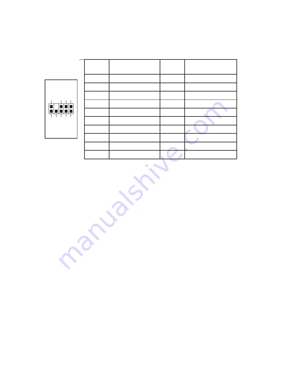
Pin Assignment for Audio Ports (HDA and AC’97)

Locate the internal audio connectors from your motherboard or sound card. 
Consult your motherboard or sound card manual for the pin-out positions.

3.5” Device Installation

There is a hard disk cage right under the external 5.25” drive. You can mount four 
hard drives using the trays inside it. 

1.     Open the front bezel as described in Setting Up section.
2.

Loosen the two thumbscrews. Swing open the fan cage and gently lift the 
cage upward to remove it. You will see four drive trays with soft silicon 
grommets inside the cage.

3.

Squeeze the metal clips on each side of the tray and slide the tray out.

4.

Mount your hard drive into the drive tray through the bottom rubber 
grommets with the special screws provided. 

Note:

Don’t over-tighten the 

screws. Over-tightening the screws will reduce the vibration and noise-
dampening ability of the rubber grommets.

5.     Slide and lock the tray back into the case.
6.

Find the appropriate power connector on the power supply and connect it to 
the connector on the device.

7.

Repeat the same procedure for the other devices as necessary. 

8.

Put the front fan cage back to the case.  If you plan to mount the optional 
92mm case fans, do it now. See The Cooling section for fan installation.

5.25” Device Installation

There are four external 5.25” drive bays (one with 5.25” to 3.5” Adapter).
Carefully remove the metal plate covering the drive bay.

Pin

Signal Names 

(HDA)

Pin

Signal Names 

(AC’97)

1

MIC2 L

1

MIC In 

2

AGND

2

GND

3

MIC2 R 

3

MIC Power 

4

AVCC

4

NC

5

FRO-R

5

Line Out (R) 

6

MIC2_JD

6

Line Out (R)

7

F_IO_SEN

7

NC

8

Key (no pin)

8

Key (no pin)

9

FRO-L

9

Line Out (L)

10

LINE2_JD

10

Line Out (L)

1

2

3

5

7

9

4

6

10

Содержание TITAN 550 550

Страница 1: ...Atlas 550 Quiet Mini Server Case User s Manual Manuel de l utilisateur Anwenderhandbuch Manuale per l operatore Manual del usuario পᡅ䂀ᯢ ...

Страница 2: ...nergy efficiency reduces heat improves output voltage stability and prolongs the life of all equipment The PSU s high efficiency design and quiet fan deliver not only a cleaner but also a quieter operating environment Although care has been taken to prevent sharp edges in your Antec case we strongly recommend taking your time and the appropriate care when working with it Hurried or careless motion...

Страница 3: ... tor detach the 4 pin attachment on the 24 pin power connector see pictures 1 and 2 2 Connect the Reset switch labeled RESET SW to your motherboard at the RST connector 3 Connect the 4 pin molex connector from the front display to a 4 pin molex connector on the power supply 4 The Power Switch labeled POWER SW connector connects to the PWR connector on the motherboard 5 The Hard Drive LED labeled H...

Страница 4: ...Intel standard connector that is keyed so that it can t be accidentally reversed when connected to a proper Intel standard motherboard header Connect the 10 pin connector to the motherboard header so that the blocked pin fits over the missing header pin Note Please check the motherboard manual for your IEEE 1394 header pin layout and make sure it matches the table below If you intend to connect th...

Страница 5: ...he tray and slide the tray out 4 Mount your hard drive into the drive tray through the bottom rubber grommets with the special screws provided Note Don t over tighten the screws Over tightening the screws will reduce the vibration and noise dampening ability of the rubber grommets 5 Slide and lock the tray back into the case 6 Find the appropriate power connector on the power supply and connect it...

Страница 6: ...tions below The fan is installed so that the air is blowing out of the case Connect a large 4 pin connector from the power supply to the male 4 pin connector on the fan Note The minimum voltage to start the fan is 5V We recommend that our users set the fan speed to High if you choose to connect the fan to a fan control device or to the Fan Only connector found on some of Antec s power supplies A f...

Страница 7: ...be installed so that the air is blowing into the case We recom mend using Antec 92mm TriCool fans to balance quiet performance with maxi mum cooling See our web site for product information Note Please choose your fan speed wisely In most cases a medium or even low speed setting will be enough to supply adequate cooling ...

Страница 8: ...0 10 462 2060 fax 31 0 10 437 1752 Customer Support US Canada 1 800 22ANTEC customersupport antec com Europe 31 0 10 462 2060 europe techsupport antec com www antec com Copyright 2007 Antec Inc All rights reserved All trademarks are the property of their respective owners Reproduction in whole or in part without written permission is prohibited Printed in China ...

Отзывы: