background image

13 
 

2.8 


Internal 3.5” Device Installation 


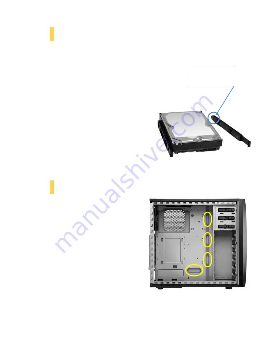
The Three Hundred Two includes 6 pairs of 3.5” drive rails. You will need 1 pair per 3.5” drive. 
 

1.


Line up the drive rail pins to the sides of your 3.5” 
drive. Ensure that the squeeze-tabs are aligned on the 
side of your drive that does not have power or data 
connectors. 

2.


Snap the rail into place. 

3.


Repeat steps 1-2 for the other side of the 3.5” drive. 

4.


Pinch the ends of the drive rails together and slide the 
drive into the 3.5” bay until it locks into position. 


2.9 


Cable Management 

 
There is a cable management compartment between the 
motherboard and right side panel. You can tuck excess 
cables in this compartment or route them to the drive 
bays through one of the four conveniently-placed cable 
management holes. 
 
Choose the cables you would like to pass through the 
holes behind the motherboard tray. Pull them through 
the hole toward the right side of the case. Feed the cables 
back through the insertion point nearest the destination 
of the cable.  


This is the drive rail pin 

that is inserted into 

your 3.5” drive hole 

Pinch the ends of the drive rails and then slide your drive into the 3.5

” 

bay until it locks into position.


Содержание Three Hundred Two

Страница 1: ...1 Three Hundred Two User Manual ...

Страница 2: ...e sure you choose a power supply that is compatible with your computer components and has a long enough power harness to reach your motherboard and peripheral devices We recommend our High Current Gamer or Earthwatts power supplies for the latest ATX specification compliance broad compatibility and power savings capability At Antec we continually refine and improve our products to ensure the highe...

Страница 3: ...lers 10 2 5 Power Supply Installation 10 2 6 External 5 25 Device Installation 11 2 7 Internal 2 5 Device Installation 12 2 8 Internal 3 5 Device Installation 13 2 9 Cable Management 13 2 10 Expansion Slot Device Installation 14 Section 3 Front I O Ports 3 1 USB 3 0 16 3 2 AC 97 HD Audio Ports 16 3 3 Power Switch Reset Switch Hard Disk Drive LED Connectors 17 3 4 Rewiring Motherboard Header Connec...

Страница 4: ...4 Section 1 Introduction Three Hundred Two User Manual ...

Страница 5: ...tandard 5 1 x 140 mm top TwoCool fan standard 6 2 x 120 mm front intake fans optional 7 1 x 120 mm side intake fan optional 8 1 x 120 mm side exhaust fan behind motherboard optional 9 8 expansion slots 10 CPU cutout 11 Motherboard mount Standard ATX microATX or Mini ITX 12 Power supply mount 13 Front ports 2 x USB 3 0 Audio In Out ...

Страница 6: ...ards optional Drive Bays 3 x 5 25 tool less drive bays 6 x 3 5 tool less drive bays 2 x 2 5 drive bays Expansion Slots 8 Motherboard Size Standard ATX microATX Mini ITX Front I O Panel 2 x USB 3 0 with internal motherboard connector Audio In Out Power and Reset buttons located on top panel of chassis 1 3 Included Screws An inventory of all screws and intended usage and quantity is provided here A ...

Страница 7: ...7 Section 2 Hardware Installation Three Hundred Two User Manual ...

Страница 8: ...arate edges or lift the sides of the chassis as paint chipping or injury may occur Place the panel thumbscrews aside in a safe place 2 2 Removing the Side Panels and Front Bezel To remove the left and right side panels 1 Remove each of the two thumbscrews first 2 Remove the panel by gripping the tab at the rear of the panel and pull it backward slightly then swing the panel outward 3 Exercise caut...

Страница 9: ... positioned for Standard ATX motherboards but can be relocated to accommodate other form factors 1 Align the motherboard with the standoff holes on the motherboard tray and remember or mark which holes are lined up 2 Install standoffs as needed B in Section 1 3 and put the motherboard in 3 Screw your motherboard into the standoffs with the provided motherboard mounting screws Note If you plan on u...

Страница 10: ...he tubes positioned at the bottom of the radiator 1 Remove the rear fan by unscrewing the fan from the back of the chassis 2 Preparing the KUHLER H2O backplate is specific to your CPU socket Please refer to the KUHLER H2O installation guide available at http www antec com Believe_it product php id Mjc2OCYxNw KUHLER H2O 620 or http www antec com Believe_it product php id NzA0MzcwJjE3 KUHLER H2O 920...

Страница 11: ...ush cover out the front of the bezel 3 Replace the front bezel on the front of the chassis 4 Slide your 5 25 drive through the front of the chassis until it lines up flush with the front bezel You will feel the drive lock into position 5 If you need more clearance on the inside of the chassis for your drive pull the drive bay tab on the inside of the chassis toward you and push the drive in furthe...

Страница 12: ...rews provided C in Section 1 3 Your drive will attach on the back of the motherboard tray with screws affixing from the front of the tray Note The motherboard should not be installed when installing your 2 5 device in this location To install at the base of the case 1 Remove the left side panel as described in Section 2 2 2 Secure your drive to the base of your case with the 2 5 screws provided C ...

Страница 13: ...locks into position 2 9 Cable Management There is a cable management compartment between the motherboard and right side panel You can tuck excess cables in this compartment or route them to the drive bays through one of the four conveniently placed cable management holes Choose the cables you would like to pass through the holes behind the motherboard tray Pull them through the hole toward the rig...

Страница 14: ...t first remove the rear place covering the expansion slots 1 With the rear of the case facing you remove the 2 screws shown to remove the plate 2 Install your expansion cards according to the manufacturer s instructions 3 Repalce the plate and screws Remove these screws prior to expansion card installation ...

Страница 15: ...15 Section 3 Front I O Ports ...

Страница 16: ...eader to the motherboard port Be sure to align the connector in the proper orientation so that you do not damage the pins on your motherboard 3 2 AC 97 HD Audio Ports There is an Intel standard 10 pin AC 97 connector and an Intel 10 pin HDA High Definition Audio connector linked to the front panel of the chassis You can connect either the AC 97 or the HDA connector depending on your motherboard Lo...

Страница 17: ...nectors on your motherboard Consult your motherboard manual for specific pin header locations For LEDs colored wires are positive White or black wires are negative If the LED does not light up when the system is powered on try reversing the connection For more information on connecting LEDs to your motherboard see your motherboard user s manual Note Polarity positive and negative does not matter f...

Страница 18: ...ires you need to remove in order to rewire your plug to match the USB pin outs on your motherboard refer to your motherboard user s manual Working on one connector at a time use a very small flathead screwdriver or similar tool to lift up on the black tab located beside the gold posts squares This will allow you to easily slide out the pins from the USB plug Working carefully so as not to damage t...

Страница 19: ...19 Section 4 Cooling System Three Hundred Two User Manual ...

Страница 20: ... 2V Speed RPM Input Current Airflow Static Pressure Acoustic Noise Input Power High 1200 0 20A Max 1 2 m min 42 6 CFM 0 96 mm H2O 0 037 inch H2O 23 7 dBA 2 4W Low 600 0 10A 0 6 m min 21 3 CFM 0 24 mm H2O 0 009 inch H2O 17 0 dBA 1 2W 140 mm TwoCool Specifications Size 140 x 25 mm TwoCool Rated Voltage 12V Operating Voltage 10 8V 13 2 V Speed RPM Input Current Airflow Static Pressure Acoustic Noise ...

Страница 21: ...n the fan with the screw holes and screw in the fan in the top left and lower right holes as pictured 3 Screw in the long fan screws D in Section 1 3 Side 120 mm fan 120 mm fan behind motherboard On both the left and right side panels there are fan mounts for 120 mm intake exhaust fans for graphics cards and CPU cooling respectively 1 Align your fan with the mounting holes 2 Screw in the fan with ...

Страница 22: ...inside facing you with the drive bay covers to the right 3 Starting from the left side use your thumbs to push the first two tabs out while using your index fingers to pull the filter away from the bezel 4 Repeat Step 3 on the right side of the filter The filter will come free of the bezel To remove the PSU filter 1 Pulling the filter out toward you using the tab outside the chassis Push out on th...

Страница 23: ...tel 49 40 226139 22 fax 31 0 10 437 1752 Technical Support US Canada 1 800 22ANTEC customersupport antec com Europe 31 0 10 462 2060 europe techsupport antec com www antec com Copyright 2012 Antec Inc All rights reserved All trademarks are the property of their respective owners Reproduction in whole or in part without written permission is prohibited ...

Отзывы: