background image

Antaira Technologies - Industrial Ethernet Switches 

LMX-2602G-SFP Series Hardware Manual V1.0 


10 


2.10  Wiring the Fault Alarm Contact 

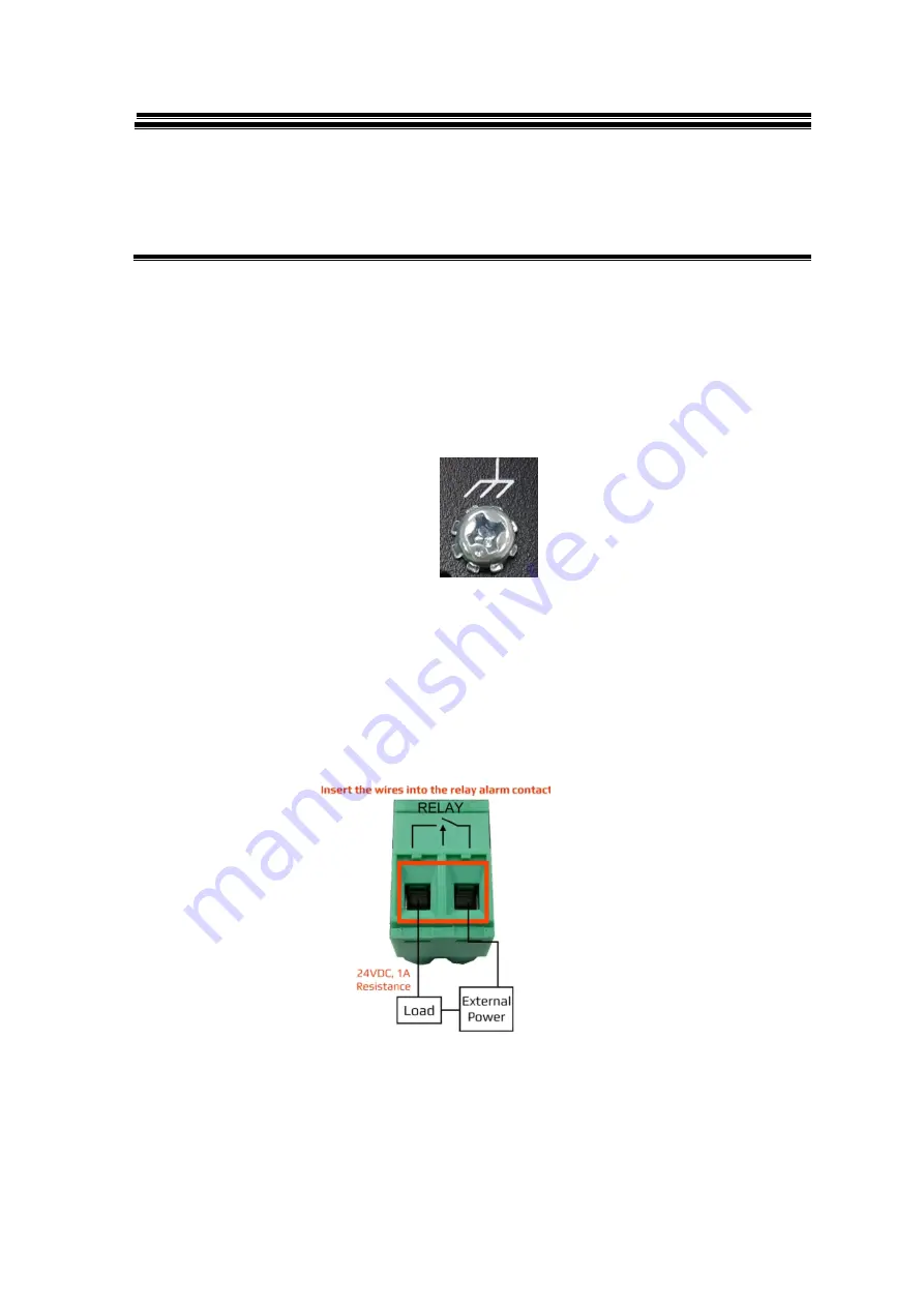
The relay contact of the 2-pin terminal block connector as the picture shows below in 

Figure 2.12

 is used to 

detect user-configured events. The two wires attached to the fault contacts form an open circuit when a 

user-configured event is triggered (managed industrial switch only). If a user-configured event does not 

occur, the fault circuit remains closed 

Figure 2.12 

Wiring the Fault Alarm Contact 

Note   

● The wire gauge for the terminal block should range between 12 ~ 24 AWG 

Note


 Only use copper conductors, 100

°

C, tighten to 5 lbs. 


 The wire gauge for the terminal block should range between 18~20 AWG


To eliminate power fault alarm, jumper Pin 1 to Pin 5 and Pin 2 to Pin 6 when using 

only one power supply 


2.9 Grounding Note 

Grounding  and  wire  routing  help  limit  the  effects  of  noise  due  to  Electromagnetic  Interference  (EMI). 

Run  the  ground  connection  from  the  ground  screw  to  the  grounding  surface  prior  to  connecting 

devices. The grounding screw symbol is shown blow in Figure 2.11. 


Figure 2.11 - Grounding screw 

Содержание LMX-2602G-SFP Series

Страница 1: ...G SFP Series 26 Port Industrial Gigabit Managed Ethernet Switch with 24 10 100 1000Tx RJ45 Ports and 2 Gigabit Combo Ports 2 10 100 1000Tx RJ45 and 2 100 1000 SFP Slots Hardware Manual Version 1 0 Apr...

Страница 2: ...ers Notice Copyrights 2020 by Antaira Technologies LLC All rights reserved Reproduction adaptation or translation without prior permission of Antaira Technologies LLC is prohibited except as allowed u...

Страница 3: ...ich can be determined by turning the equipment off and on the user is encouraged to try to correct the interference by one or more of the following measures Reorient or relocate the receiving antenna...

Страница 4: ...1 5 Safety Precaution 3 2 Hardware Description 4 2 1 Physical Dimensions 4 2 2 Front Panel 5 2 3 Rear Panel 5 2 4 LED Indicators 6 2 5 Reset Button 7 2 6 Ethernet Ports 7 2 7 Cabling 8 2 8 Wiring the...

Страница 5: ...the market s open standard ITU T G 8032 ERPS Ethernet Ring Protection Switch protocol that has a 50ms network recovery time The advanced network filtering and security functions such as IGMP VLAN QoS...

Страница 6: ...ckup USB Port 1 3 Product Hardware Features System Interface and Performance All RJ45 ports support Auto MDI MDI X Function Embedded 24 10 100 1000Tx RJ45 Ports and 2 Gigabit Combo Ports 2 10 100 1000...

Страница 7: ...trial Ethernet switch s hardware specs ports cabling information and wiring installation will be described within this user manual Warning Labels The caution label means that you should check the cert...

Страница 8: ...2602G SFP Series Hardware Manual V1 0 4 2 Hardware Description 2 1 Physical Dimensions Figure 2 1 below shows the physical dimensions of Antaira s LMX 2602G SFP series W x D x H is 440mm x 200mm x 44m...

Страница 9: ...gure 2 3 below shows the top panel of the LMX 2602G SFP series switch that is equipped with one 8 connector redundant power inputs 90 264VAC and one 2 pin terminal block for replay output Figure2 3 To...

Страница 10: ...ional SFP Port with combo port LINK ACT Port 25 26 Green On Connected to network Flashing Networking is active with 1000Mbps Off Not connected to network Amber On Connected to network Flashing Network...

Страница 11: ...ult LED is flashing with green and red color 8s t press time Backup configuration to USB startup config LED is flashing with red color Table 2 2 Reset Button Functions 2 6 Ethernet Ports RJ45 Ports Au...

Страница 12: ...tation etc must be less than 100 meters 328 ft long Note Cable size should be between 18 20 AWG and the torque should be tightened to 5lbs The small form factor pluggable SFP is a compact optical tran...

Страница 13: ...transceiver and pull it out to release as shown below in Figure 2 8 2 Push down the metal clasp and pull the transceiver out by the plastic part as shown below in Figure 2 9 2 8 Wiring the Power Inpu...

Страница 14: ...it remains closed Figure 2 12 Wiring the Fault Alarm Contact Note The wire gauge for the terminal block should range between 12 24 AWG Note Only use copper conductors 100 C tighten to 5 lbs The wire g...

Страница 15: ...ure it with the smaller plate screws Then attach the remaining plate to the other side of the switch 2 After attaching both mounting plates position the switch in the rack by lining up the holes in th...

Страница 16: ...n 5 Insert one side of the RJ45 cable into switch s Ethernet port and on the other side into the networking device s Ethernet port e g switch PC or server The Ethernet port s RJ45 LED on the industria...

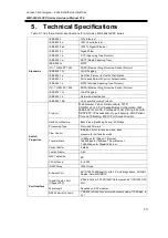
Страница 17: ...2 1AB Link Layer Discovery Protocol Switch Properties Protocol Web browser Telnet Serial console TFTP SNMPv1 v2c v3 Port Speed Duplex Configuration IPv6 IEEE 802 1Q GVRP Port based VLAN X Ring 802 1w...

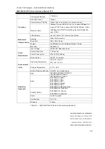
Страница 18: ...nt Input Power Connection 1 AC socket Power Consumption Max 24W full loading Relay Contact 24VDC 1A resistive Environmental Limits Operating Temperature STD 10 to 65 C EOT 40 to 75 C Storage Temperatu...

Страница 19: ...ernet Switches LMX 2602G SFP Series Hardware Manual V1 0 15 www antaira com support antaira com www antaira eu info antaira eu www antaira com tw info antaira com tw Any changes to this material will...

Отзывы: