background image

Web Remote Control

9-3 Web Remote Control Interface

Site Master User Guide

PN: 10580-00252  Rev. K

9-7

Depending on the browser and operating system used, different prompts may appear. Some 
operating systems like iOS may not support file saving from a browser.

File List

Displays the list of folders and files contained in the instrument's internal memory. You can 
select from the list the files or folders you wish to download to your PC or mobile device. Refer 
to 

“File List” on page 9-9

.

Device Management

Opens 

“Device Management” on page 9-10

, where you can set the instrument password and 

assign a name to the instrument.

Logout

Exits Web Remote Control and displays the login page. To return to Web Remote Control, 
enter the password or leave the field blank if no password has been set, then select the 
session time and click 

Login

. Se

Figure 9-2 on page 9-4

.

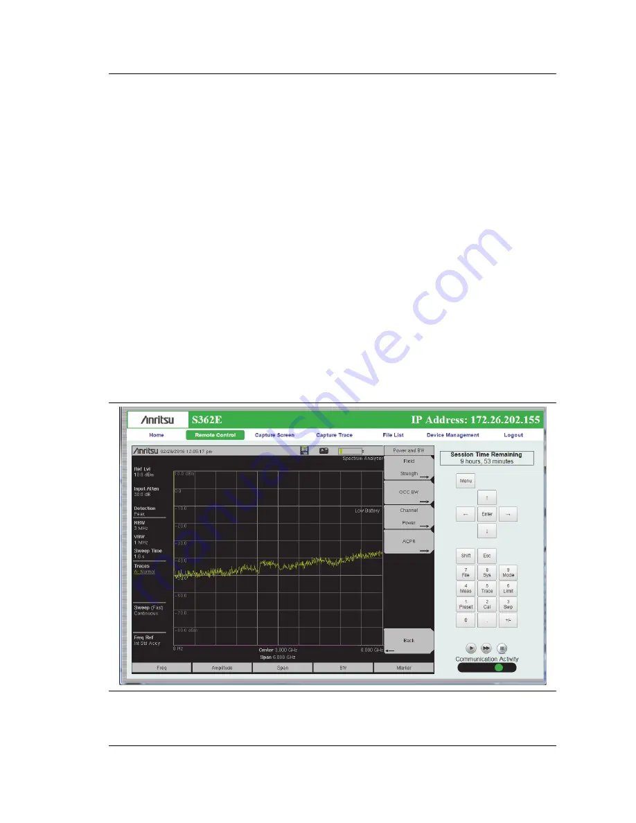
Remote Control

The Remote Control instrument display shows a bitmap image of the instrument screen. The 
buttons on the right of the display reflect the layout of the buttons on the instrument and are 
used to access the same monitoring and control functions. See 

Figure 9-6

Figure 9-6.

Remote Control Page

Содержание S331E

Страница 1: ...trum Analyzer 100 kHz to 6 GHz Appendix A provides a list of supplemental documentation for the Site Master features and options The documentation set is available as PDF files on the documentation disc and the Anritsu website Anritsu Company 490 Jarvis Drive Morgan Hill CA 95037 2809 USA http www anritsu com Part Number 10580 00252 Revision K Published March 2016 Copyright 2016 Anritsu Company ...

Страница 2: ......

Страница 3: ...nment Workplace 1 7 Site Master Memory Types 1 7 Erase All User Files in Internal Memory 1 7 Recommended Usage in a Secure Environment 1 7 Chapter 2 Instrument Overview 2 1 Introduction 2 1 2 2 Turning On the Site Master 2 1 2 3 Instrument Front Panel 2 2 LED Indicators 2 2 Front Panel Keys 2 3 2 4 Interface Screen 2 6 Touch Screen Keys 2 8 Symbols and Icons on the Title Bar 2 8 Symbols and Indica...

Страница 4: ...alibration 3 6 3 4 Spectrum Analyzer 3 7 Set Start and Stop Frequencies 3 7 Enter the Center Frequency 3 7 Select a Signal Standard 3 7 Set the Measurement Frequency Bandwidth 3 7 Set the Amplitude 3 8 Power Offset Set Up for Compensating External Loss 3 8 Set the Span 3 8 Single Limit Line 3 9 Create a Limit Envelope 3 9 Setting Up Markers 3 10 Select a Measurement Type 3 11 External Power On 3 1...

Страница 5: ... Power On Menu 5 6 Display Settings Menu 5 7 Brightness Settings Menu 5 8 Reset Menu 5 9 5 4 Preset Menu 5 10 5 5 Self Test 5 10 5 6 Updating the Site Master Firmware 5 11 Chapter 6 GPS Option 31 6 1 Introduction 6 1 6 2 Activating the GPS Feature 6 1 6 3 Resetting GPS 6 3 6 4 Saving and Recalling Traces with GPS Information 6 3 Saving Traces with GPS Information 6 3 Recalling GPS Information 6 3 ...

Страница 6: ... Setup 9 1 LAN Connection 9 1 Connection to a Wi Fi Portable Router 9 2 9 3 Web Remote Control Interface 9 4 Menu Bar 9 6 Remote Control 9 7 File List 9 9 Device Management 9 10 Logout 9 11 Appendix A Measurement Guides A 1 Introduction A 1 Appendix B LAN and DHCP B 1 Introduction B 1 B 2 LAN Connection B 1 B 3 Ethernet Configuration B 1 Ethernet Menu B 2 DHCP B 4 B 4 ipconfig Tool B 5 B 5 Ping To...

Страница 7: ...http www anritsu com en US test measurement products s332e http www anritsu com en US test measurement products s361e http www anritsu com en US test measurement products s362e Document Part Number Description Required Option 10100 00065 Important Product Information Compliance and Safety Notices 10580 00349 Spectrum Analyzer Measurement Guide Interference Analyzer Option 25 Channel Scanner Option...

Страница 8: ...4 in TFT color display provides easy viewing in a variety of lighting conditions All Site Master models are equipped with a Li Ion battery delivering more than four hours of battery life for the S331E S361E and more than three hours of battery life for the S332E S362E Site Masters The combination of a touch screen and keypad enables users to navigate menus with the touch screen and enter numbers w...

Страница 9: ...ntact us Table 1 2 Available Options S331E S332E S361E S362E Description S331E 0010 S332E 0010 S361E 0010 S362E 0010 Bias Tee Requires Option 21 on S331E and S361E S331E 0019 S332E 0019 S361E 0019 S362E 0019 High Accuracy Power Meter 1 S331E 0021 S332E 0021 S361E 0021 S362E 0021 2 Port Transmission Measurement S332E 0025 S362E 0025 Interference Analyzer 2 S332E 0027 S362E 0027 Channel Scanner S332...

Страница 10: ... rings Repair or replace damaged connectors immediately Dirty connectors can limit the accuracy of your measurements Damaged connectors can harm the instrument Connection of cables carrying an electrostatic potential excess power or excess voltage can damage the connector the instrument or both Connecting Procedure 1 Carefully align the connectors The male connector center pin must slip concentric...

Страница 11: ...as temporarily attaching a short or load device to the cable or antenna prior to attaching to the Site Master It is important to remember that the operator may also carry a static charge that can cause damage Following the practices outlined in the above standards will ensure a safe environment for both personnel and equipment Battery Replacement The battery can be replaced without the use of tool...

Страница 12: ...rger Refer to Symbols and Indicators on page 2 9 for a description of battery symbols Figure 1 1 Battery Compartment Note Use only Anritsu Company approved batteries adapters and chargers with this instrument Anritsu recommends removing the battery for long term storage of the instrument Caution When using the Automotive Power Adapter always verify that the supply is rated for a minimum of 60 Watt...

Страница 13: ...ent along with current measurements This memory is reset whenever the instrument is restarted External USB Flash Drive not included with the instrument This memory may be selected as the destination for saved measurements and setups for the instrument The user can also copy the contents of the internal disk on chip memory to the external flash memory for storage or data transfer The external Flash...

Страница 14: ...creen 5 Press the Set Location submenu key The external USB drive is now the default location for saving files Note Not all USB drives are compatible with the instrument Many drives come with a second partition that contains proprietary firmware This partition must be removed Only one partition is allowed Refer to the individual manufacturer for instructions on how to remove it Some drives can be ...

Страница 15: ...rom a 12 VDC source which will simultaneously charge the battery This can be achieved with either the Anritsu AC DC Adapter or the Automotive Power Adapter Both items are included as standard accessories with the Site Master Refer to the instrument Technical Data Sheet To turn on the Site Master press the green On Off button on the front panel see Figure 2 1 on page 2 2 The Site Master takes appro...

Страница 16: ...dicators Power LED The Power LED is located on the left of the On Off button The LED is solid green when the instrument is on and blinks slowly when the unit is off but is connected to an external power source Charge LED The Charge LED is located on the right of the On Off button The LED blinks slowly when the battery is charging and is solid green when the battery is fully charged Figure 2 1 Site...

Страница 17: ...utes the function that is indicated in blue above the number key When the Shift key is active its icon is displayed at the far right of the title bar above the sweep window Esc Key Press this key to cancel the parameter change being made and exit the current menu function if applicable Arrow Keys The four arrow keys are used to scroll through a list and highlight the item you wish to select or to ...

Страница 18: ...s to change modes These icons are preinstalled and cannot be moved or deleted An alternative to the Menu key is to press Shift then the Mode 9 key to display the Mode Selector list box Refer to Mode Selector on page 2 16 Figure 2 3 Menu Key Screen Note Shortcut icons displayed in the top rows of the Menu screen vary with the instrument model firmware version and installed options Help for the Menu...

Страница 19: ...ss Recall under the File menu then press and hold the desired file name until a grid is displayed Select the display location of the new shortcut as described above User defined shortcuts remain on the Menu screen until deleted To delete or move a shortcut icon press the Menu key then press and hold the shortcut until the Customize Button dialog appears See Figure 2 5 Press the appropriate button ...

Страница 20: ...itle bar and measurement settings and results around the graph area or sweep window Figure 2 6 Cable and Antenna Analyzer Return Loss Measurement Display 1 Measurement Settings Summary 2 Calibration Status Type 3 Frequency Standard 4 Date and Time 5 GPS Icon 6 GPS Location 7 Save Icon 8 Save Screen Icon 9 Battery Charge Indicator 10 Trace Measurement Title 11 Submenu Touch Screen Keys 12 Main Menu...

Страница 21: ...andard 3 Date and Time 4 GPS Icon 5 GPS Location 6 Save Icon 7 Save Screen Icon 8 Battery Charge Indicator 9 Trace Measurement Title 10 Submenu Touch Screen Keys 11 Main Menu Touch Screen Keys 12 Marker Table Note Many of the measurement settings displayed to the left and the top of the sweep window are actually touch screen shortcuts that you can press to bring up the corresponding menu 1 2 11 12...

Страница 22: ...lays the system date and time When GPS is on and is tracking satellites its icon is followed by latitude and longitude coordinates Press the storage icon to open the touch screen keyboard for saving measurements setups limit lines or screen display JPEG files This shortcut to the Save Menu on page 4 11 is equivalent to pressing Shift and File 7 then Save Refer to Save Dialog Box on page 4 3 Press ...

Страница 23: ...olt Battery is being charged any color symbol Red Plug body External power is applied and no battery is installed or battery has lost communications with the instrument Storage Icon Tap the floppy disk icon to display the Save screen and menu Camera Icon Saves a JPEG image of the current screen display Shift Key Icon This icon is displayed between the battery symbol and the submenu keys after the ...

Страница 24: ...tton three times in rapid succession In addition to the default display colors shown in Figure 2 7 on page 2 7 you can select different color schemes to suit the ambient lighting conditions See Figure 2 9 Some color settings may not be available in all measurement modes Black on White used for printing and viewing in broad daylight conditions Night Vision optimized for nighttime viewing High Contr...

Страница 25: ...2 11 The shortcut can be used if your touch inputs do not correspond to the appropriate locations on the screen to such an extent that you cannot access the Calibrate Touch Screen submenu key Disable Touch Screen to Use Arrow Navigation If the touch screen is not functioning you can use Arrow Navigation to simulate pressing the touch screen main menu keys and submenu keys From the touch screen cal...

Страница 26: ...mes are determined by the current setting of the Save Measurement As submenu key Refer to Save Measurement As on page 4 10 You can save a JPEG image of the current display screen by pressing Shift followed by Decimal then The JEPG image shows screen data but does not contain the additional measurement information that accompanies a saved measurement in a spa measurement file To return to normal to...

Страница 27: ...nts This is a Standard calibration indicating it is not possible to change the frequency range after calibration without performing another calibration Cal Status ON Flex Insta The Site Master has been calibrated with the InstaCal module This is a FlexCal calibration indicating it is possible to change the frequency range after calibration Cal Status ON Standard Insta The Site Master has been cali...

Страница 28: ...n the measurement mode refer to the associated Measurement Guide listed in Appendix A for a description of available menus and submenus Numeric Values To modify a numeric parameter setting that is displayed on a submenu touch screen key press the key to make it active The display color of the currently set value changes to red Use the rotary knob arrow keys or the numeric keypad to change the valu...

Страница 29: ... for a measurement or setup file you wish to save a touch screen keyboard is displayed See Figure 2 13 Digits can be entered using the touch screen keyboard or the front panel keypad The left and right arrow keys move the insertion point in the file name edit box Refer to Save Dialog Box on page 4 3 for information on saving files Figure 2 13 Touch Screen Keyboard ...

Страница 30: ...t box illustrated in Figure 2 14 Use the directional arrow keys or the rotary knob to highlight the desired mode then press Enter to switch to the selected application The measurement modes available for selection depend on the options that are installed and activated on your instrument An alternate method of selecting a measurement mode is through the use of the Menu Key on page 2 4 Figure 2 14 M...

Страница 31: ...igure 2 15 S332E Connector Panel 1 External Reference In 2 External Trigger In 3 Analyzer RF In Type N 4 USB Mini B 5 GPS Type SMA Option 31 6 External Power 7 USB Type A 8 Headset jack 9 Option 411 RJ45 Ethernet Connector see Figure 2 16 Option 751 SFP Optical Module Connector see Figure 2 17 10 RF Out Type N Figure 2 16 RJ45 Ethernet Connector Option 411 1 2 3 4 5 6 7 8 9 10 ...

Страница 32: ...displayed until the next trigger signal arrives Analyzer RF In 50 Ω Type N female connector Maximum input is 33 dBm at 50 VDC USB Interface Mini B The USB 2 0 Mini B connector can be used to connect the Site Master directly to a PC The first time the Site Master is connected to a PC the normal USB device detection by the computer operating system will take place GPS Antenna Connector Option 31 The...

Страница 33: ...tor is used to connect the Site Master to a local area network or directly to a PC with an Ethernet crossover cable Integrated into this connector are two LEDs The amber LED shows the presence of a 10 Mbit s LAN connection when on and a 100 Mbit s LAN connection when off The green LED flashes to show that LAN traffic is present For more information on the LAN connection Ethernet connection and DHC...

Страница 34: ... panel fully closed and laying flat 3 Open the zippered back of the case 4 Insert the instrument face down into the case take care that the connectors are properly situated in the case top opening You may find it easier to insert the connectors first then pull the corners over the bottom of the Site Master 5 Close the back panel and zipper to secure the Site Master Note The soft case has two zippe...

Страница 35: ...r improved stability To deploy the tilt bail pull the bottom of the tilt bail away from the back of the instrument To store the tilt bail push the bottom of the bail towards the back of the instrument until it attaches to the Site Master Caution The soft case has panel openings for the fan inlet and exhaust ports Do not block the air flow through the panels when the unit is operating Note Do not u...

Страница 36: ...2 9 Tilt Bail Stand Instrument Overview 2 22 PN 10580 00252 Rev K Site Master User Guide ...

Страница 37: ... refer to the appropriate Measurement Guide as listed in Appendix A 3 2 Measurement Mode Selection Press the Menu key then press the shortcut icon for the desired application or measurement mode See Figure 3 1 Alternatively you can press Shift followed by the Mode 9 key then select the measurement mode from the Mode Selector list box Figure 3 1 Menu Key Screen Note The application shortcuts displa...

Страница 38: ... the arrow keys to enter the start frequency 3 Press the Stop Freq submenu key and use the keypad rotary knob or the arrow keys to enter the stop frequency Set the Amplitude 1 Press the Amplitude main menu key 2 Press the Top submenu key and use the keypad rotary knob or the arrow keys to edit the top scale value Press Enter to set 3 Press the Bottom submenu key and use the keypad rotary knob or t...

Страница 39: ...e selected marker is shown above the upper left corner of the graph It is also possible to drag the marker using the touch screen 4 Delta Markers are available for each of the six reference markers For the selected marker Toggle the Delta On Off submenu key to turn on the Delta marker Peak Valley Auto Markers When making Return Loss and VSWR measurements the Peak Valley Auto feature can be used to...

Страница 40: ...e Limit On Off key to turn on the Limit 3 Press Single Limit and then use the numeric keypad the arrow keys or the rotary knob to change the limit value and then press Enter 4 Press the Limit Alarm key to turn on or off the Limit Alarm Note Refer to the Cable Antenna Measurement Guide listed in Appendix A for creating multi segment limit lines Figure 3 3 Single Limit Lines ...

Страница 41: ...e DTF parameters a Set Start Distance and Stop Distance Stop Distance needs to be smaller than Dmax b Enter the Start and Stop frequencies c Press Cable select the appropriate cable from the cable list and press Enter d Press Continue 5 Press Shift then Calibrate 2 to calibrate the instrument Refer to Calibrate with OSL Calibration on page 3 6 for additional information 6 Press the Marker main men...

Страница 42: ...t Short to RF Out and press the Enter key 7 Connect Load to RF Out and press the Enter key 8 Verify that the calibration has been properly performed by checking that the Cal Status message is now displaying ON Standard or ON FlexCal Note Refer to the Cable Antenna Measurement Guide listed in Appendix A for calibration details Figure 3 5 Calibration Setup with OSL Cal Power Charge 0 3 Sweep 2 Calib...

Страница 43: ...equency using the keypad the arrow keys or the rotary knob When entering a frequency using the keypad the submenu key labels change to GHz MHz kHz and Hz Press the appropriate unit key Pressing the Enter key has the same affect as pressing the MHz submenu key The center frequency and span is shown at the bottom of the screen Select a Signal Standard 1 Press the Freq main menu key 2 Press the Signa...

Страница 44: ...factor is in dB External attenuation can be created by using an external cable or an external high power attenuator Press the RL Offset submenu key and use the keypad the arrow keys or the rotary knob to enter the desired offset value When using the rotary knob the value changes in increments of 0 1 dB Using the Left Right arrow keys changes the value in 10 increments of the value shown on the Sca...

Страница 45: ...o that On is underlined 3 Press the Limit Move submenu key to display the Limit Move menu Press the first Move Limit submenu key and use the arrows keys rotary knob or keypad to change the dBm level of the limit line 4 Press the Back submenu key to return to the Limit menu 5 If necessary press the Set Default Limit submenu key to redraw the limit line in view Create a Limit Envelope 1 Press Shift ...

Страница 46: ...red frequency 4 Repeat steps 1 through 3 to activate and move additional markers Selecting Activating and Placing a Delta Marker 1 Press the Marker 1 2 3 4 5 6 submenu key and select the desired delta marker The selected marker is underlined 2 Press the Delta On Off submenu key so that On is underlined The selected marker is displayed in red and ready to be moved 3 Use the rotary knob to place the...

Страница 47: ...eature is enabled the Site Master in the off state will turn on when external DC power is applied The instrument turns off when external power is removed even if a battery is installed This is useful for high reliability remote operation where the instrument may need to be rebooted using a remotely controlled power switch If the instrument is turned on with the power switch then external power is ...

Страница 48: ...3 4 Spectrum Analyzer Quick Start Guide 3 12 PN 10580 00252 Rev K Site Master User Guide ...

Страница 49: ...in basic instrument information measurement mode setup details measurement marker data and limit data Measurement spa dat vna ia cs edg wcd tds cdma evdo wmxd wmxe afp Measurement files contain all of the information in the setup files and the measurement data File extensions are determined by the current measurement mode and selected file type JPEG jpg Image file is a screen capture of the curren...

Страница 50: ...asurement As shows the default file name for the next measurement to be saved as ACPR_1 then ACPR_2 and so on To save using a different file name than the default press the Save Measurement key or the Save key instead of Save Measurement As Save Measurement To save the current measurement data use the Save Measurement As submenu key described above or to apply a different file name or save locatio...

Страница 51: ...r to select Press Enter again to save the file File name extensions are automatically assigned based on the file type and measurement mode Refer to File Types on page 4 1 Quick Name Keys Quick Name keys in the Save dialog provide optional building blocks for entering file names They function as keyboard shortcuts allowing you to enter predefined frequently used file names or parts of file names To...

Страница 52: ...e Figure 4 4 Similarly to the Quick Name keys the matrix gives field personnel a shortcut method to enter file names in compliance with carrier requirements which may include file naming conventions related to site number sector information color coding measurement type termination device or frequency information See Figure 4 5 Figure 4 4 Save Dialog Box Cable and Antenna Analyzer Mode Figure 4 5 ...

Страница 53: ...nsert separators in the file name 5 Repeat Step 4 as needed until the file name is complete Note that the Keyboard key see Figure 4 5 on page 4 4 closes the Quick Name Matrix screen and returns to the Save dialog The next steps can be performed from either screen 6 Select the file type to save either from the drop down list or by using the Change Type submenu key 7 Optionally press the Change Save...

Страница 54: ... type Refer to Save On Menu on page 4 13 Recall Files Press the Recall Measurement key or the Recall key under the File menu to recall a previously saved file from internal memory or an external USB drive if connected The files listed in the Recall dialog box depend on the file type selected See Figure 4 7 JPEG image files cannot be recalled The submenu keys let you change the file types and sort ...

Страница 55: ... to copy are listed in the top pane of the Copy dialog box Select the destination in the bottom pane See Figure 4 8 1 To copy to or from an external USB drive insert the flash drive into a USB port on the instrument Otherwise skip to the next step 2 Press the Shift key followed by File 7 then press the Copy submenu key 3 Use the submenu keys to select the type of file to copy and the display order...

Страница 56: ...iles or folders Items to be deleted may be in the instrument s internal memory or an external USB drive if connected However you cannot select files and folders located in different drives simultaneously The files listed in the Delete dialog box depend on the chosen file type which is selected using either the Filetype drop down list or the File Type submenu key You can also change the way folders...

Страница 57: ...resh Directories Recall Clear All Save On Crossing Limit On Off Sweep Complete On Off Save Then Stop On Off B A File Type ALL Select or De Select Delete Refresh Directories Delete B Sort By Name Type Date Scroll Src Dst File Type ALL Refresh Directories Select or De Select Copy Copy A Create Folder Set Location Refresh Directories Save Location Save Change Type Setup JPEG Change Save Location Reca...

Страница 58: ...ve Location Menu on page 4 12 Save Press this submenu key to display the Save Menu and Save dialog box The available settings are the same as those of the Save Measurement key Save on Event Not available in all measurement modes Press this submenu key to display the Save On Menu on page 4 13 Recall Measurement Press this submenu key to display the Recall Menu on page 4 14 Use this menu to recall m...

Страница 59: ...touch screen keyboard see Figure 4 13 Select the Quick Name to edit then press Enter Type the new Quick Name and press Enter again The new Quick Name is displayed on the button below the keyboard Change Save Location Press this submenu key to open the Save Location Menu where you can set the location of the destination file for saved data Change Type Setup JPEG Press this submenu key to open the S...

Страница 60: ... 4 6 on page 4 5 Sort Order Ascend Descend Press this key to toggle the sort order of the folder list between Ascending and Descending Create Folder Press this submenu key to create a new folder inside the selected directory Enter the new folder name in the Create Directory dialog and press Enter To return to the Select Save Location dialog without creating a new folder press Esc Set Location Pres...

Страница 61: ...en specified with the Limit menu Sweep Complete On Off When this key is set to On measurement data is automatically saved after the current sweep is completed Save Then Stop On Off Set this key to On to stop the sweep after a measurement is saved If this setting is Off and Sweep Complete is On a measurement is saved after every sweep Clear All Press this key to turn Off all three Save On Event key...

Страница 62: ...een Ascending and Descending File Type Press this submenu key to open the Select File Type list box Press the desired file type on the list then press Enter to apply the selection JPEG image files cannot be recalled and are not listed Alternatively you can select directly from the Filetype drop down list in the Recall dialog box Refresh Directories Press this key to update the file list after conn...

Страница 63: ...resh Directories Press this key to update the file list after connecting or disconnecting an external USB drive Scroll Src Dst Press this submenu key to shift navigation control between the source and destination panes in the Copy dialog box Select or De Select Press this key to select or deselect the current file or folder Selected items are highlighted in blue Copy Copies the selected files and ...

Страница 64: ...he list then press Enter to apply the selection Alternatively you can select directly from the Filetype drop down list in the Delete dialog box Select or De Select Press this key to select or deselect the current file or folder Selected items are highlighted in blue Delete Deletes the selected files or folders which are highlighted in blue In the confirmation box press Yes to delete No to cancel Y...

Страница 65: ...52 Rev K 5 1 Chapter 5 System Operations 5 1 Introduction This chapter reviews the Site Master system operations and related menus The other menus Sweep Measure Trace and Limit are described in the Measurement Guides listed in Appendix A ...

Страница 66: ... DHCP Field IP G Way Sub First Octet Second Octet Third Octet Fourth Octet 1 Reset System Options Date Time Language Name Volume Ethernet Config More Display Back Reset Factory Defaults Master Reset Update Firmware 2 2 Back Display Settings Brightness Display Blank Default Colors 3 3 Back System Options 2 2 Share CF Pwr Offset All Modes Not Shared Set Remote Access Password Power On Requires Optio...

Страница 67: ... related to the performance of the instrument for specific applications A display will list the individual tests with a pass or fail indication Press Esc or Enter to return to normal operation GPS Opens the GPS Menu on page 6 4 Calibrate Touch Screen If the instrument does not respond as expected when you press the touch screen press this key to display the touch screen calibration message box Ref...

Страница 68: ...h language captions using Master Software Tools MST If a mode does not have language translations available then English is the default language Caution A firmware update or any instrument reset will overwrite modifications you may have made in any of the language files Display The Display submenu key opens the Display Settings Menu on page 5 7 allowing brightness control and the selection of diff...

Страница 69: ...w password Passwords may contain digits uppercase and lowercase letters and the symbols _ hyphen underscore plus period Press Enter to save or Esc to cancel Setting the remote password and rebooting the instrument will lock it from Telnet and FTP connections This means that connecting to the instrument via Master Software Tools v2 21 1 or later Wireless Remote Tools WRT or the Web Remote Control b...

Страница 70: ...submenu key to set the instrument for normal use of the On Off button on the instrument front panel When DC Applied Press this submenu key to set the instrument to automatically restart when DC power is applied to the External Power connector see Figure 2 15 on page 2 17 Back Press this submenu key to return to the System Options 2 2 Menu on page 5 5 Figure 5 6 Power On Menu Back Power On Power Sw...

Страница 71: ... broad daylight conditions See Figure 2 9 on page 2 10 for illustrations of the display color schemes selectable in this submenu Night Vision Sets the display to a red tinted color on a black background The front panel keypad is backlighted in red This setting is optimized for nighttime viewing High Contrast Increases the black and white contrast of the default display This setting is used in chal...

Страница 72: ... Auto Dim On Off Press this submenu key to toggle the display auto dimming feature on and off Enabling auto dim can extend battery life Auto Dim Delay Press this key to adjust the amount of idle time from 1 to 15 minutes before the instrument display goes dim Use the arrow keys or the rotary knob to adjust the value in increments of 1 You can also use the numeric keypad then press Enter Out of ran...

Страница 73: ... factory defaults and to delete all user files from the instrument internal memory The instrument will power cycle as part of this operation Press the Enter key to initiate the reset or press Esc to abort Update Firmware Press this submenu key to update the instrument operating system using an external USB drive Press Load Firmware to start the update procedure or press the Menu key to cancel and ...

Страница 74: ...ts are displayed 3 Press Esc to close the Self Test results dialog Preset This key resets the instrument to the default starting conditions Save Setup Opens the Save dialog box see Figure 4 1 on page 4 2 to name and save the current operating settings allowing them to be recalled later to return the instrument to the state it was in at the time the setup was saved The saved setup can be named usin...

Страница 75: ...e Site Master off and insert the memory stick into the instrument 5 Connect the AC adapter and turn on the Site Master 6 The instrument should update automatically Follow the instrument prompts 7 If the automatic update did not start complete the following steps a On the instrument press the Shift key then the System 8 key b Press the following key sequence System Options Reset Update Firmware The...

Страница 76: ...5 6 Updating the Site Master Firmware System Operations 5 12 PN 10580 00252 Rev K Site Master User Guide ...

Страница 77: ...cquired 6 2 Activating the GPS Feature Attach the GPS antenna to the GPS Antenna connector on the top of the instrument 1 Press the Shift key then the System 8 key on the numeric keypad to display the System menu 2 Press the GPS submenu key 3 Activate GPS by pressing the GPS On Off submenu key so that On is underlined When GPS is first turned On the GPS icon is displayed in red to indicate that fe...

Страница 78: ...l Standard Accuracy or a user selected external reference frequency in the Status menu Within three minutes of satellite acquisition the reference oscillator will have an accuracy of better than 25 ppb parts per billion The OCXO internal standard accuracy is 0 3 PPM The correction factor applied to the internal OCXO allows the instrument to maintain GPS frequency accuracy for three days at better ...

Страница 79: ... key 6 4 Saving and Recalling Traces with GPS Information Saving Traces with GPS Information The GPS coordinates of a location can be saved along with a measurement trace Refer to Save Menu on page 4 11 for more information The current GPS coordinates will be saved with the measurement traces whenever GPS is on and actively tracking satellites Recalling GPS Information If the GPS coordinates were ...

Страница 80: ... data so the receiver does not have a current almanac A complete system almanac is not required to achieve a first position fix However UTC time is not correct until the almanac is complete and the availability of the almanac can significantly reduce the time to first fix Antenna Status OK Active antenna is connected and is working properly Short Open If an active antenna is in use a short or open...

Страница 81: ...e used to power some tower mounted amplifiers The bias can be turned on only when the instrument is in transmission measurement return loss cable loss VSWR DTF or spectrum analyzer mode When bias is turned on the bias voltage and current are displayed in the lower left corner of the display The 12 VDC to 32 VDC power supply is designed to continuously deliver a maximum of 6 watts The bias tee menu...

Страница 82: ...7 1 Overview Bias Tee Option 10 7 2 PN 10580 00252 Rev K Site Master User Guide ...

Страница 83: ...D or you can download individual applications from the Anritsu website at anritsu com en US test measurement support technical support handheld tools tool box This chapter gives an overview of the software installation DVD and the main features of each application in the Anritsu Tool Box 8 2 Software Installation DVD Place the software disc in the DVD drive on your PC and follow the on screen inst...

Страница 84: ...ion from which you can open a previously saved measurement visit the Anritsu website or launch an application To open the Tool Box either double click the desktop shortcut or select the Tool Box from the Windows Start menu under All Programs and the Anritsu folder On the Tool Box screen hover the mouse pointer over any of the application icons to view a short description of the application See Fig...

Страница 85: ...C Marker and limit line presets Return Loss Distance to Fault PIM analysis LMR Master and VNA Master Field Mode compatibility Plot overlay for comparison of up to ten traces of the same measurement type Plot area zooming A naming grid for renaming files titles and subtitles Automated report generation Output to printer or to PDF or HTML format Export of plot data to text image or VNA files Master ...

Страница 86: ...ved manually or automatically easyMap Tools easyMap Tools is the new name for Anritsu Map Master The application allows users to find and prepare geo referenced maps and to build floor plans suitable for Anritsu Handheld Spectrum Analyzers with Interference Analysis or Coverage Mapping capabilities Option 25 or Option 431 respectively Software functions include Creation of geo referenced maps with...

Страница 87: ...multiple users can view the same instrument using a desktop sharing application 9 2 Setup You can connect one or more instruments through direct connection a LAN or portable router to any device with an HTML 5 browser Current versions of Google Chrome and Mozilla Firefox are supported The device may be a laptop a desktop computer or a mobile device including a wide range of tablets and smart phone...

Страница 88: ...ple 1 Take note of the router s SSID and pre programmed password which are found on a sticker affixed to the router 2 Using the Ethernet cable included with the router connect one end to the black LAN port and the other end to the test instrument s Ethernet port 3 Insert the Mini B small end of the provided USB cable into the router and the Type A larger end of the cable into one of the USB ports ...

Страница 89: ...Web Remote Control 9 2 Setup Site Master User Guide PN 10580 00252 Rev K 9 3 Figure 9 1 Setting IP Address Manually ...

Страница 90: ...ting the instrument is currently being used by another client If you try again after one minute the current user s session will be terminated and you will then have control of the instrument Upon successful connection the Web Remote Control Home page displays on your PC or mobile device as illustrated in Figure 9 3 on page 9 5 Information displayed on the Home page is the same as the System Status...

Страница 91: ...K 9 5 At the top of the browser window a green title bar shows the instrument model number and IP address If the instrument has been assigned a name this name is displayed in the center of the title bar The menu bar consists of tabs for commands and links Figure 9 3 Web Remote Control Home Page ...

Страница 92: ... stamp Only the instrument display will be pictured on the Web page under the menu bar See Figure 9 4 In Windows you can right click on the screen and select Copy With iOS press and hold on the picture This makes it easy to create documentation using screen captures Capture Trace Opens an input dialog to enter a name for the trace to be saved See Figure 9 5 After clicking Save a confirmation dialo...

Страница 93: ...e 9 9 Device Management Opens Device Management on page 9 10 where you can set the instrument password and assign a name to the instrument Logout Exits Web Remote Control and displays the login page To return to Web Remote Control enter the password or leave the field blank if no password has been set then select the session time and click Login See Figure 9 2 on page 9 4 Remote Control The Remote...

Страница 94: ... instrument will return to Normal mode Pause Mode Clicking the Pause button turns the Communication Activity dot in the lower right hand corner to yellow If the interface was in Normal Mode this stops the instrument display from refreshing in the browser window If the interface was in Fast Mode the trace measurement stops updating Click the single arrow or the double arrow button to resume remote ...

Страница 95: ...eckboxes of multiple files and or folders and download them together as a zipped folder In this case a pop up dialog box shows the estimated download time Press OK to continue Depending on the browser and operating system the download function may allow you to open the file or save it or both In Google Chrome for example the downloaded file or files are automatically saved to the designated folder...

Страница 96: ...er Software Tools MST provided the application is installed Device Management Click the Device Management tab on the menu bar to set or clear the instrument password or to assign a device or unit name to the instrument See Figure 9 8 Password If no password is set access to the instrument is unrestricted and any user who knows the instrument IP address can connect to it provided the instrument is ...

Страница 97: ...you have more than one instrument connected The name can be assigned remotely from this Device Management page or it can be set from the instrument s System Options menu Note that this instrument name is not a hostname as used in an Ethernet router Session Time Use the pull down menus to select the time in hours and minutes before the remote session times out At the end of the selected time period...

Страница 98: ...9 3 Web Remote Control Interface Web Remote Control 9 12 PN 10580 00252 Rev K Site Master User Guide ...

Страница 99: ...ion 25 Channel Scanner Option 27 C W Signal Generator Option 28 Gated Sweep Option 90 Coverage Mapping Option 431 AM FM PM Analyzer Option 509 Spectrum Analyzer Measurement Guide 10580 00349 High Accuracy Power Meter Option 19 Power Meter Option 29 Power Meter Measurement Guide 10580 00240 Cable and Antenna Analyzer Cable and Antenna Analyzer Measurement Guide 10580 00241 Bias Tee Option 10 2 Port...

Страница 100: ...A 1 Introduction Measurement Guides A 2 PN 10580 00252 Rev K Site Master User Guide ...

Страница 101: ...n off The green LED flashes to show that LAN traffic is present B 3 Ethernet Configuration The instrument IP address is set by pressing the Shift key then the System 8 key followed by the System Options submenu key and the Ethernet Config submenu key The instrument Ethernet address can be set automatically using DHCP or manually by entering the static IP address gateway address and subnet mask Dyn...

Страница 102: ... the rotary knob to enter the values Press Enter to accept the changes or press the Esc key to exit Ethernet Configuration without making changes Field IP G Way Sub Press this submenu key to select the desired Internet Protocol Property to be edited First Octet Moves the cursor to the leftmost column of the selected IP properties field Second Octet Moves the cursor to the second column from the le...

Страница 103: ...LAN and DHCP B 3 Ethernet Configuration Site Master User Guide PN 10580 00252 Rev K B 3 Figure B 2 Setting IP Address Manually Figure B 3 IP Address Assigned Using DHCP ...

Страница 104: ...network always request the static IP address from the network administrator Randomly choosing a static IP address on an established network may result in duplicate IP addresses or other conflicts Three parameters must be set prior to using a static IP address IP Address This is the static IP address on the network Static IP addresses are necessary when you have no physical access to the instrument...

Страница 105: ... some determinations about the network to which the PC is connected Typing ipconfig at a command prompt produces a display of information about the in use parameters of the PC and its network connection Following is an example of the typical results expected Y ipconfig Windows 2000 IP Configuration Ethernet adapter Local Area Connection Connection specific DNS Suffix us anritsu com IP Address 172 ...

Страница 106: ...a valid connection is found then a copy of the signal that was sent is returned If a connection is not found then the response is request timed out which means that no reply was received from that IP address Y ping 172 26 202 172 Pinging 172 26 202 172 with 32 bytes of data Reply from 172 26 202 172 bytes 32 time 10ms TTL 128 Reply from 172 26 202 172 bytes 32 time 10ms TTL 128 Reply from 172 26 2...

Страница 107: ...and dynamically adapts signal patterns to optimize wireless system performance The arrays use signal processing algorithms to adapt to user movement to changes in the radio frequency environment and to multi path and co channel interference ADC Analog to Digital Converter ADC A D or A to D is an electronic device that converts continuous signals to discrete digital numbers The reverse operation is...

Страница 108: ...e relative gain of the main beam of an antenna pattern to a reference antenna usually an isotropic or standard dipole Antenna Gain is the effectiveness of a directional antenna expressed as the ratio of input power of the directional antenna to input power of an isotropic radiator to provide the same field strength in the desired direction Sometimes related to a dipole antenna Antenna Isotropic An...

Страница 109: ...rmation Each radio channel has a center frequency and additional frequencies above and below this carrier frequency which is used to carry the transmitted information The range of frequencies from the lowest to the highest used is called the bandwidth Bandwidth Ratio Bandwidth Ratio is the ratio of two devices having differing bandwidths not necessarily in the same frequency spectrum BER Bit Error...

Страница 110: ...pters are all accounted for For optimal performance high quality phase stable cables and precision adapters must be used CCDF Complementary Cumulative Distribution Function CCDF is a method used to characterize the peak power statistics of a digitally modulated signal The CCDF curve can be used to determine design parameters for CDMA systems such as the amount of back off to run in a power amplifi...

Страница 111: ...er conductor concentric to an inner conductor separated from each other by insulating material and covered by some protective outer material This medium offers large bandwidth supporting high data rates with high immunity to electrical interference and a low incidence of errors Coax is subject to distance limitations and is relatively expensive and difficult to install Configuration Commands Confi...

Страница 112: ... Decibel or deciBel dB is a logarithmic ratio of the difference between two values a logarithm ratio is equal to 10 times dB is a unit for measuring relative power ratios in terms of gain or loss The units of dB are expressed in terms of the logarithm to base 10 of a ratio and typically are expressed in watts For example a 3 dB loss indicates a 50 loss in power a 3 dB reading is a doubling of powe...

Страница 113: ...trument output connector or the end of a test lead to a problem area as indicated by a peak in the displayed signal DTF measures the location and reflection size of impedance mismatches This is typically a diagnostic measurement not a pass fail judgement measurement DTF is used to identify and locate faults within an antenna system when the system is failing to meet the specified return loss or VS...

Страница 114: ... DFT and its inverse FFTs are of great importance to a wide variety of applications from digital signal processing to solving partial differential equations to algorithms for quickly multiplying large integers Flash Memory Flash memory is a non volatile solid state storage device that is packaged as a chip It can be electrically erased and reprogrammed It is primarily used in memory cards USB flas...

Страница 115: ...ency IF is a frequency to which a carrier frequency is shifted as an intermediate step in transmission or reception An intermediate electromagnetic frequency is generated by a superheterodyne radio receiver Impedance Impedance is a measure of RF component electricl resistance measured in ohms In most cable and antenna systems the standard impedance is 50 ohms Insertion Loss Insertion Loss or Cable...

Страница 116: ...3 567C 8 1 where FFFF Hex 65535 Dec Ea hexadecimal group nnnn represents values from 0000 to FFFF or binary values of 16 bits 0000 0000 0000 0000 to 1111 1111 1111 1111 LPA Linear Power Amplifier LPA is the final amplification stage in a multicarrier transmitter that has been designed and optimized to produce a linear response By operating in the linear mode the amplifier reduces the non linear ef...

Страница 117: ...iently manipulates line sweep and PIM traces for reporting purposes MHz Megahertz MHz One MHz is equal to one million Hertz and is a measurement of frequency NF Noise Figure NF is a measure of degradation of the signal to noise ratio SNR that is caused by components in a radio frequency RF device The noise factor F of a system is defined as the signal to noise ratio of the input power of the syste...

Страница 118: ... RBW With spectrum analyzers a narrow band filter is swept across a frequency span to create the spectrum display The filter bandwidth RBW determines the frequency resolution across the frequency axis Remote Access Point Remote Access Point also known as relay access points is one of a number of secondary access points in a wireless network that uses Wireless Distribution System WDS to extend its ...

Страница 119: ...Calibration Compare this with SSLT or Offset Short 1 Offset Short 2 Load Thru calibration method for waveguide line types SSL SSL or Short Short Load or Offset Short 1 Offset Short 2 Load calibration method for waveguide line types uses Shorts with different offset lengths It is a calibration common in waveguide with simple and redundant standards but it is band limited It requires well defined st...

Страница 120: ... as close as practical to the antenna in Base Transceiver Stations or in mobile masts When using a TMA the antenna is able to receive weaker signals VBW Video Bandwidth VBW VSWR Voltage Standing Wave Ratio VSWR VSWR is another method to measure reflected energy caused by impedance mismatch It is expressed as a ratio of X 1 VSWR measures the voltage peaks and valleys A ratio of 1 1 would be a perfe...

Страница 121: ...olor on white 5 7 community activity 9 8 connection LAN 9 1 router 9 2 connector panel 2 17 contacting Anritsu 1 2 copy menu 4 15 create folder 4 12 custom language settings lost with reset 5 4 D date and time key 5 4 default display colors 5 7 gateway for IP address B 4 DHCP LAN connection B 1 more information B 4 display auto dim 5 8 brightness 5 8 turn off 5 7 display key 5 4 DVD 8 1 Dynamic Ho...

Страница 122: ...guage settings lost 5 4 Master Software Tools 8 3 measurement guides A 1 measurements saving in arrow navigation 2 12 menu copy 4 15 delete 4 16 Ethernet B 2 file 4 10 file type 4 12 GPS 6 4 mode selector 2 16 Power On 5 6 preset 5 10 recall 4 14 reset 5 9 save 4 11 save location 4 12 save on 4 13 save on event 4 13 system 5 3 system options 5 4 5 7 system options 2 2 5 5 MST See Master Software T...

Страница 123: ... 19 share center freq and power offset key 5 5 Software Tool Box 8 1 8 2 static IP address setting parameters B 4 subnet B 1 subnet mask for IP address B 4 system menu 5 2 system options 2 2 menu 5 5 system self test 5 10 T tilt bail 2 21 Tool Box 8 1 8 2 touch screen calibration 2 11 U USB connectors 2 19 V volume key 5 4 W web links product page 5 11 Web remote control 9 1 website contacting Anr...

Страница 124: ...Index 4 PN 10580 00252 Rev K Site Master User Guide ...

Страница 125: ......

Страница 126: ...Anritsu Company 490 Jarvis Drive Morgan Hill CA 95037 2809 USA http www anritsu com Anritsu utilizes recycled paper and environmentally conscious inks and toner ...

Отзывы: