


1-5 IEEE-488 Interface Bus Description
General GPIB Information
1-4
PN: 10370-10374 Rev. F
MG369xC GPIB PM
Functional Elements
Effective communications between devices on the GPIB requires three functional elements; a
talker
, a
listener
,
and a
controller
. Each device on the GPIB is categorized as one of these elements depending on its current
interface function and capabilities.
Talker
A talker is a device capable of sending device-dependent data to another device on the bus when
addressed to talk. Only one GPIB device at a time can be an active talker.
Listener
A listener is a device capable of receiving device-dependent data from another device on the bus when
addressed to listen. Any number of GPIB devices can be listeners simultaneously.
Controller
A controller is a device, usually a computer, capable of managing the operation of the GPIB. Only one
GPIB device at a time can be an active controller. The active controller manages the transfer of
device-dependent data between GPIB devices by designating who will talk and who will listen.
System Controller
The system controller is the device that always retains ultimate control of the GPIB. When the system is
first powered-up, the system controller is the active controller and manages the GPIB. The system
controller can pass control to a device, making it the new active controller. The new active controller, in
turn, may pass control on to yet another device. Even if it is not the active controller, the system
controller maintains control of the Interface Clear (IFC) and Remote Enable (REN) interface
management lines and can thus take control of the GPIB at anytime.
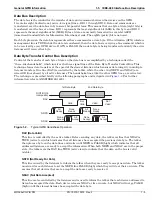
Bus Structure
The GPIB uses 16 signal lines to carry data and commands between the devices connected to the bus.
The interface signal lines are organized into three functional groups.
•
Data Bus (8 lines)
•
Data Byte Transfer Control Bus (3 lines)
•
General Interface Management Bus (5 lines)
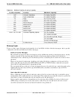
The signal lines in each of the three groups are designated according to function.
lists these
designations.
Table 1-1.
Interface Bus Signal Line Designations
Bus Type
Signal Line Name
Function
Data Bus
DIO1–DIO8
Data Input/Output, 1 thru 8
Data Byte Transfer Control Bus
DAV
Data Available
NRFD
Not Ready For Data
NDAC
Not Data Accepted
General Interface Management Bus
ATN
Attention
IFC
Interface Clear
SRQ
Service Request
REN
Remote Enable
EOI
End Or Identify
Содержание MG369 C Series
Страница 2: ......
Страница 6: ...Contents 4 PN 10370 10374 Rev F MG369xC GPIB PM ...
Страница 262: ...A 34 PN 10370 10374 Rev F MG369xC GPIB PM ...
Страница 264: ...Index 2 PN 10370 10374 Rev F MG369xC GPIB PM ...
Страница 265: ......


