


Using the Power Sensor
Graphical User Interface
MA24104A UG
PN: 10585-00016, Rev. A
3-3
Buttons
There are nine buttons available on the user interface to perform the most common tasks as described below:
• Zero: Performs the Zero operation. Removes system noise from the measurement.
• Hold/Run: Holds the last reading. Run releases the hold.
• Frequency: Applies frequency correction to the measured power.
• Power Units: Displays units of power in linear or log scale.
• Normal/Relative: Displays power changes with respect to a desired reference value.
• Averages: Allows input of a custom averaging entry. The default number is 1.
• Fixed Offset: Applies an offset in dB. Input positive value for attenuation.
• Apply: Applies the current entry in the data entry field.
• Exit: Terminates the program.
Data Entry Fields
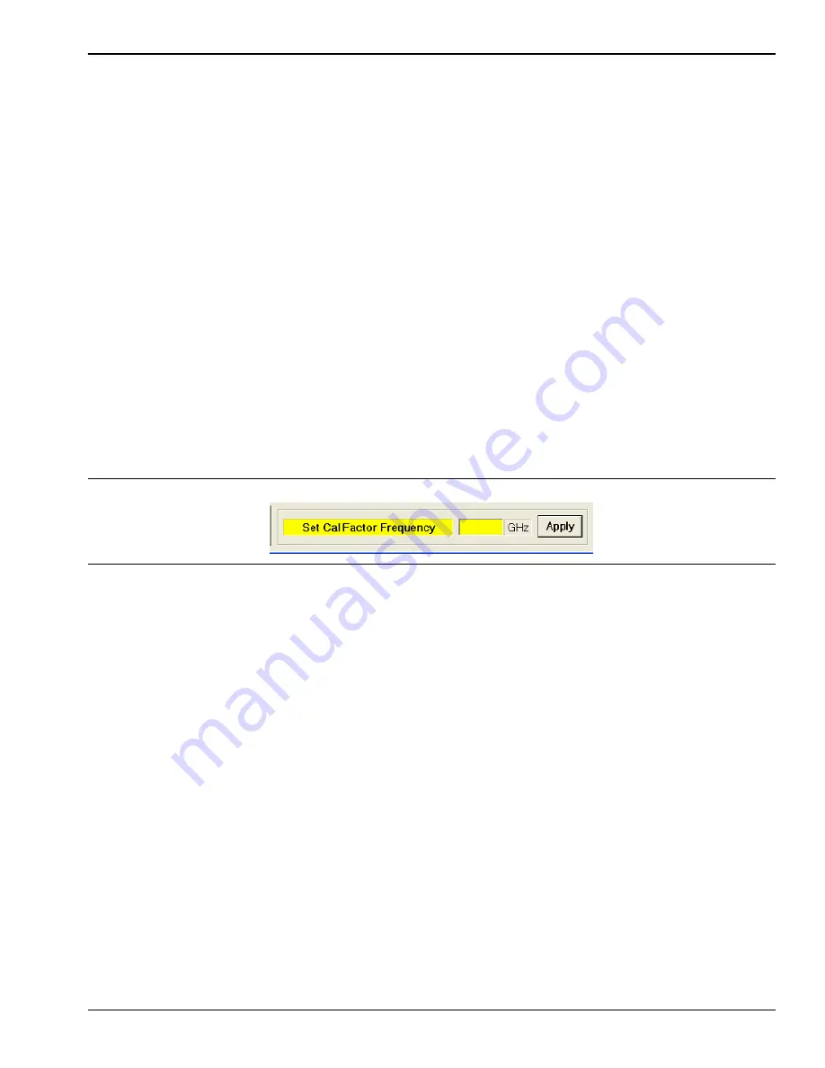
The data entry fields become active when clicking a button to accept an appropriate entry (see the example in
Figure 3-3). Communication with the power sensor does not take place until the Apply button is clicked or the
Enter key on the keyboard is pressed. The following list summarizes the entry fields:
• Frequency Button: Sets the Cal Factor Frequency in GHz
• Power Units Button: Sets the units of power to dBm, W, mW, or µW
• Averages Button: Sets the number of averages from 1 to 256 (see Table 3-1 for guidelines)
• Fixed Offset Button: Sets the offset from –100 dB to +100 dB
Figure 3-3.
Example of an Active Entry Field