Operator’s
Manual
pg.
16
Rev
E
4/2/12
21. Pull the Main Handle downward, closing and locking the Extraction Vessel in
place. You will hear a click noise when the Safety Valve Pin locks in place.
IMPORTANT
Before running the instrument, verify that the Extraction Vessel is locked in place by
attempting to rotate the Main Handle upward. If it is not locked, follow step #20 above.
22. Verify that the water supply is on.
23. Press START on the Keypad. The instrument will run through its automatic operation, showing its status
on the Display.
24. When the instrument has completed its automatic operation, the Display will read:
“Remove/Insert Samples
Enter
.”
At this time, the only light shining on the Display should be the green power
light.
25. When the Pressure Gauge reads zero, remove the Extraction Vessel by pushing down on the Safety Valve
Handle to release the locking pin and then rotating the Main Handle to the open position.
26. Use the Extraction Vessel Handle to remove the Extraction Vessel.
Warning:
The Extraction Vessel interior and top will be
HOT
when the
extraction process is complete.
27. Remove the Teflon Insert from the Extraction Vessel.
28. Clean the fat from the bottom of the vessel using paper towel.
IMPORTANT
If too much fat accumulates in the bottom of the Extraction Vessel, an overtemp fault will
occur.
29. Remove the Bag Holder from the Teflon Insert.
30. Remove the filter bags from the Bag Holder.
31. Dry the samples in an oven at 102°C±2° for 30 minutes.
32. Remove the samples from the oven and place them in a Desiccant Pouch.
33. Allow the samples to cool to room temperature. This should take about 10 – 15
minutes.
34. Re-weigh each filter bag (W
3
) immediately after removing from the Desiccant Pouch.
Содержание XT10
Страница 2: ...This page intentionally left blank ...
Страница 4: ...This page intentionally left blank ...
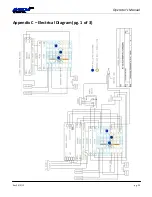
Страница 25: ...Operator s Manual Rev E 4 2 12 pg 25 Appendix C Electrical Diagram pg 1 of 3 ...
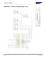
Страница 26: ...Operator s Manual pg 26 Rev E 4 2 12 Appendix C Electrical Diagram pg 2 of 3 ...
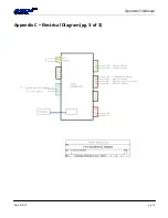
Страница 27: ...Operator s Manual Rev E 4 2 12 pg 27 Appendix C Electrical Diagram pg 3 of 3 ...


