background image

WordClock-1 Assembly Guide 12/08/19 Version 1.2 


Page 3 


  Separate the main board from the display board by bending along the V-

score line. 

  Build the power supply on the main board. Install J1, F1, C1, C2, C3, D1, D2, L1, and 

U1. Note that C1, C2, D1, and D2 must be installed in the direction noted on the board. 


  Connect a 9-12v power supply with a center positive, 2.1mm connector, and check the 

test point for 5v. Do not continue assembly if 5v is not present at the test point. 


  Install the remaining components on the main board. Start with U3, the 74AHC125D, 

14-SOHC chip. The line or dot on one side of the chip must be installed toward the 
cutout on one side of the silkscreened pattern. The best way to install a surface mount 
chip is to add a very small amount of solder to one of the corner pads for the part. 
Then quickly and carefully solder the corresponding pin to the pad. Check the 
alignment of all 14 pins and if correct, solder the opposite corner pin. Check the 
alignment again, then solder the remaining pins quickly and carefully. 


  Install the SD card connector next. Be sure to solder all leads to the board. Solder 

quickly and carefully. Plastic parts can be damaged by too much heat. Several pins on 
one side of the connector are very close to the grounded case. Be careful that they are 
only soldered to the pc board, not the case. Then install J3, the GPS connector.  


  The ambient light sensor, Q1, should be installed about 10mm above the board. The 

shorter lead goes toward the back of the board. 


  Cut the 40 pin female header into two, 19 pin pieces. Install at the U2 location.  

DO NOT solder the microcontroller to the board! 


  Install the remaining parts to the main board. J6 and J7 are not used. 


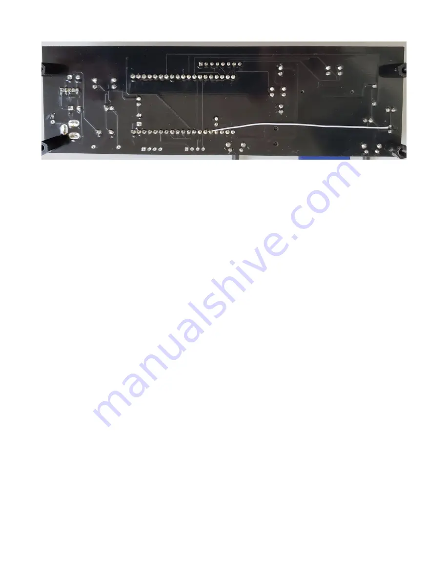
  Connect a jumper on the bottom of the board from Q1, the TEPT4400 pin farthest from 

the switch immediately behind it, to pin 5 on the microcontroller, U2, labeled IO34 or 
G34.  

Содержание WordClock-1

Страница 1: ...WordClock 1 Assembly Guide 12 08 19 Version 1 2 Page 1 WordClock 1 Assembly Guide Contents Introduction 2 Assembly 2 Bill of Materials 6 Warranty Terms and Conditions 8 Schematic 9...

Страница 2: ...IN THE CASE BASE FIRST USE THE CIRCUIT BOARD AS A TEMPLATE DO NOT INSTALL THE HEADERS FOR THE ALPHANUMERIC LEDs REMOVE THE PINS OTHERWISE THE BACKLIGHTING WILL BE BLOCKED DO NOT SOLDER THE MICROCONTRO...

Страница 3: ...lder the corresponding pin to the pad Check the alignment of all 14 pins and if correct solder the opposite corner pin Check the alignment again then solder the remaining pins quickly and carefully In...

Страница 4: ...R6 R9 These resistors are used to equalize the brightness between the display and colons If a different color colon is used this value may have to be adjusted Install C9 the surface mount capacitor to...

Страница 5: ...rection Again follow the above procedure to install surface mount parts Install LED7 LED10 the colon LEDs The short pin goes toward the top of the display board Align the colon LEDs so the top is even...

Страница 6: ...C9 1 Capacitor 100nf Surface mount 1210 marked 104 D1 1 Diode 1N4001 D2 D3 2 Zener Diode 1N5819 F1 1 Poly Fuse 500mA Labeled 050 J1 1 Power Jack 2 1mm J2 1 SD Card Connector DM1AA SF PEJ J3 1 Audio J...

Страница 7: ...re U3 1 IC 74AHC125D Quad buffer SMD U4 1 IC HT16K33 LED driver SOP28 108 Pin Female pins for 16 segment display LEDs 2 Bracket Keystone 4326 4 Standoff Threaded 10mm 6 Screw M3 8mm 2 Nut M3 1 Silver...

Страница 8: ...t forth in these terms and conditions AE s sole obligation will be at its election to repair or replace the AE kit part in question AE may require return of the part for examination and replacement Re...

Страница 9: ...WordClock 1 Assembly Guide 12 08 19 Version 1 2 Page 9 Schematic...

Страница 10: ...WordClock 1 Assembly Guide 12 08 19 Version 1 2 Page 10...

Отзывы: