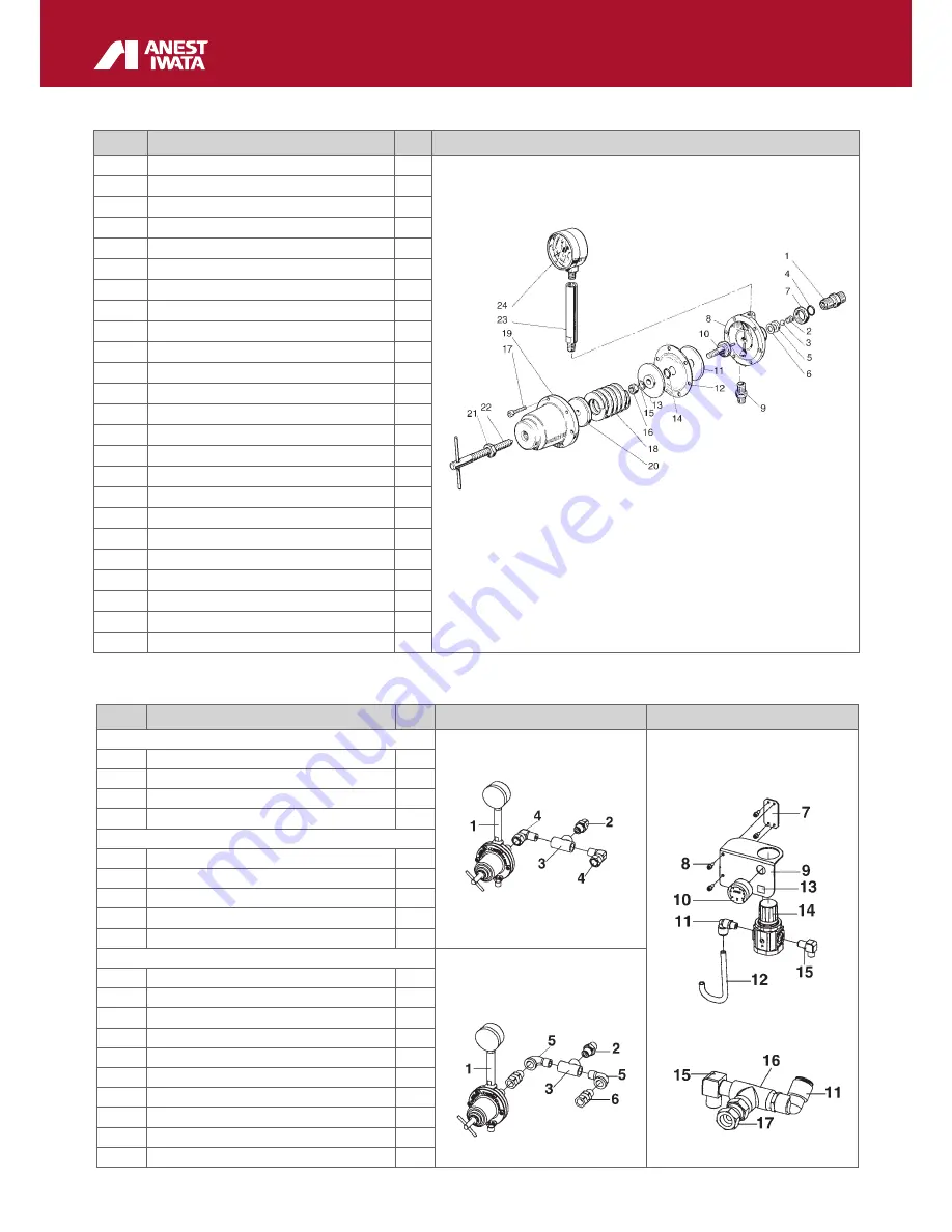
Anest Iwata DDP 70 B series Скачать руководство пользователя страница 30

30

Ref.

Description

1

JOINT G3/8” 

2

VALVE SPRING

3

CARBIDE BALL

#

4

O’RING

5

CARBIDE SEAT

#

6

PACKING

7

HEX. NUT

8

BODY

9

JOINT G1/4”-G3/8”  

10

DIAPHRAGM BOLT

11

DIAPHRAGM HOLDER

12

DIAPHRAGM

#

13

DIAPHRAGM STOPPER

14

O’RING

#

15

SPRING WASHER

16

HEXAGON NUT

17

HEX. SOCKET BOLT

18

ADJUSTING SPRING

19

DIAPHRAGM CAP

20

SPRING STOPPER

21

HEXAGON NUT

22

HANDLE SET

23

RISING PIPE

24

PRESSURE GAUGE

10.3  PAINT PRESSURE REGULATOR - A) 

PR-5BL | PR-5BLN

Ref. Description

Qty.

for ALUMINIUM TYPE

1

PAINT REGULATOR

1

2

JOINT

1

3

T-JOINT

1

4

ELBOW UNION

2

for STAINLESS STEEL TYPE

1

PAINT REGULATOR

1

2

JOINT

1

3

T-JOINT

1

5

STREET UNION

2

6

UNION JOINT M-F

2

for ALL TYPES

7

SUB PLATE

1

8

BOLT WITH HEX. HOLE

4

9

PLATE

1

10

PRESSURE GAUGE

1

11

ELBOW UNION

2

12

TUBE

1

14

AIR REGULATOR

1

15

ELBOW

2

16

T-JOINT

1

17

UNION JOINT M-F

1

10.4 

 2-WAY JOINT CONNECTION KIT - OPTIONAL

ALUMINIUM TYPE

ALL TYPES

STAINLESS STEEL TYPE

Содержание DDP 70 B series

Страница 1: ...in Zones 1 and 2 X marking Any static electricity discharge from the pump is to be diverted to the ground through the grounding wire which is included in this product Serie DDP 70 B DDP 70 B TE Alumi...

Страница 2: ...URE RELEASE PROCESS 22 8 MAINTENANCE AND INSPECTIONS 23 8 1 GENERAL NOTES 23 8 2 SAFETY RULES DURING MAINTENANCE 23 8 3 RECOMMENDED SCHEDULED OPERATIONS 23 8 4 DIAPHRAGM PUMP DISASSEMBLY FROM IT BASE...

Страница 3: ...vi cing shops The warranty covers no intervention of our technicians during installation or dismantling opertions If for practical purposes one of our technicians is sent to the premises the time plus...

Страница 4: ...ntilation can cause organic solvent intoxication or explosion due to sprayed mist of paint or solvent which catches fire If you feel any abnormality during operation consult a medical doctor immediate...

Страница 5: ...Securely connect hose to avoid leak and looseness If hose is disconnected during operation hazardous hose movement and paint ejection will cause severe bodily injury Never use cracked damaged bent cr...

Страница 6: ...CTIVE GLOVES AND SAFETY SHOES WARNING WHILE LIFTING OR HANDLING THE EQUIPMENT OR ANY OF ITS COMPONENTS CLEAR THE WORKING AREA LEAVE ALSO A SUFFICIENT SAFETY AREA AROUND THE EQUIPMENT TO AVOID DAMAGING...

Страница 7: ...ake sure it has not been damaged during tran sport or storage Also check that all standard components are inside the packaging STAND CART ALL MODEL TANK WALL PR 5BL 1 Drain hose set 1 Cart set 1 Suppl...

Страница 8: ...the manufacturer always mention the serial number written on the plate itself Equipment group II Category Gas 2G Suitable for use in zones 1 and 2 Max surface temperature temperature class T6 X markin...

Страница 9: ...00 psi Max Fluid Working Pressure 7 bar 100 psi Air Inlet G 1 4 Fluid Outlet G 3 8 Fluid Inlet G 1 4 Paint Delivery at 30 cyc min 0 6 lt min Paint Delivery at 200 cyc min 6 lt min Paint Viscosity 60se...

Страница 10: ...mount lid without tank with paint regulator 2 air regulators for pump and gun dip pipe with filter for 20L tank fluid recirculation overpressure valve ball valve with exhaust hole PR 5BL paint pressu...

Страница 11: ...mounted on wall mounting bracket with paint regulator 2 air regulators for pump and gun dip tube with filter fluid recirculation 1 over pressure valve ball valve with exhaust hole PR 5BL paint pressu...

Страница 12: ...LVE ANY TAMPERING WITH COULD BE DANGEROUS FOR THE OPERATOR AND COMPROMISE THE EQUIPMENT GOOD WORKING EXHAUST VALVE In case of anomalies during working turn 90 the exhaust valve lever In this way the a...

Страница 13: ...held responsible for any accident due to the pump use by an UNAUTHORIZED and non qualified staff using it for purposes that are different from the above mentioned ones WARNING NEVER USE THE FOLLOWING...

Страница 14: ...umatic valve reverses the operations The compressed air enters the air chamber from side B in picture 2 The diaphragm is moved to the right by pushing the paint At the same time the diaphragm on side...

Страница 15: ...the pump on a stable surface to avoid movements during use The distance between the pump and the paint height of suction must be as short as possi ble However it can vary according to viscosity and re...

Страница 16: ...page 21 2 Fix the drain hose to the suction hose with band 3 spots wherever you want B TANK MOUNTING TYPE 1 Remove the dust proof caps B E F H I on page 21 2 Assemble the supply lid in its seat conne...

Страница 17: ...s when is fitted 2 Unscrew the fitting bolt M6 from pump lower adaptor assemble the handle to lower adaptor and stand by using the same hex bolt M6 and fix the other side of the handle by using and he...

Страница 18: ...ex Bolts M6 4 Connect the drain hose to the two way valve for paint recirculation as COMMON 1 5 Connect the suction hose to the paint inlet joint Hex Bolt M6 Bracket Drain hose Suction hose E GRAVITY...

Страница 19: ...protective clothes described in section 7 3 Comply with all the local standards on electric safety and fire risks 7 3 CLOTHES Wear some protective gloves and goggles an oxygen mask and some ear protec...

Страница 20: ...p Recommended pressure about 5 0 bar 7 Adjust the paint pressure regulator as required from 0 to 3 0 bar 8 Adjust the spraying air by means of the reducer Ref D on page 21 and test the gun on a panel...

Страница 21: ...T USE THE SYSTEM UNTIL THE PROBLEM CAUSE IS IDENTIFIED Keep away from the working area all kinds of waste of solvent container of solvent or petrol soa ked rags or clothes Before starting the system d...

Страница 22: ...trol with some air under pressu re PRECAUTIONS 1 To operate the pump use some filtered air by means of an air filter with filtering section lower than 50 m We recommend using a filter with condensate...

Страница 23: ...ntenance operations at shorter intervals Every 2 000 Overhaul the whole painting unit and replace the worn components working hours Note The component corrosion speed varies according to the type of p...

Страница 24: ...fitting to rod Tightening pressure of nuts 5 9 Nm CONNECTORS LIDS DISASSEMBLY OPERATING VALVE DISASSEMBLY A Remove the 2 nuts with a 10 mm spanner B Remove the following parts from rod Nut Spring wash...

Страница 25: ...age Check the direction of the valve seat making reference to the figure below 1 Remove packing seat and steel ball 2 Replace worn or damage parts PRECAUTIONS During the reassembly of the lids on main...

Страница 26: ...19 spring stopper ref 20 adjusting spring ref 18 and diaphragm 2 Loosen jam nut ref 7 and remove joint ref 1 valve spring ref 2 ball ref 3 seat ref 5 and packing ref 6 3 Fix hex section of diaphragm...

Страница 27: ...ng ref 2 and ball ref 3 to joint ref 1 and then fit joint ref 1 to body ref 8 Tightening torque of joint 14 7N m 7 Fix joint ref 1 with jam nut ref 7 IMPORTANT Fit tungsten carbide seat to main body s...

Страница 28: ...2 19 DIAPHRAGM SET 2 IN 2 OUT 2 2 21 Y PACKING 2 22 PSD PACKING 1 23 O RING 2 24 HEX SOCKET BOLT WITH WASHER 2 25 ROD 1 27 MUFFLER 2 28 SUB PLATE 1 29 GASKET 1 30 HALF UNION 1 31 PACKING 1 10 2 DDP M...

Страница 29: ...29 DIPHRAGM PUMP UNIT DDP DIPHRAGM PUMP SET ASSY DPS B...

Страница 30: ...SET 23 RISING PIPE 24 PRESSURE GAUGE 10 3 PAINT PRESSURE REGULATOR A PR 5BL PR 5BLN Ref Description Qty for ALUMINIUM TYPE 1 PAINT REGULATOR 1 2 JOINT 1 3 T JOINT 1 4 ELBOW UNION 2 for STAINLESS STEEL...

Страница 31: ...1 4 1 7 FEMALE UNION 10 x RC1 4 1 8 SAFETY VALVE 1 10 5 AIR REGULATOR SET B Ref CART SET Qty CART SET STAND SET 1 AXLE 1 2 U BOLT WITH HEX NUT 2 4 3 SNAP PIN 4 4 WASHER 4 5 SOLID TIRE 2 6 HANDLE 1 7 H...

Страница 32: ...ION PIPE SET 1 SUCTION FILTER SET for ALL TYPES PIC 3 SUTION FILTER SET 1 1 FILTER 50 mesh 2 FILTER STOPPER DRAIN HOSE SET for CART TYPE STAND TYPE WALL BRACKET TYPE PIC 4 DRAIN HOSE SET 1 DRAIN HOSE...

Страница 33: ...ump fluid passage Remove the clogging material Every paint regulator fluid passage Remove the clogging material The pump does not run Disassemble the pump and check the following parts which will be r...

Страница 34: ...em The PTFE diaphragms Replace them PAINT OUTPUT CONTAINS AIR The following parts are unscrewed or damaged The pump suction joint N and R page 29 with suction pump Check the loosened tightening and ti...

Страница 35: ...3 Seat packing ref 6 damaged Replace packing ref 6 PAINT LEAKS OUTSIDE Loose joint ref 1 Tighten Loose bolt with hex Hole ref 17 Tighten Loose hex nut ref 16 Tighten Diaphragm damaged ref 12 Replace...

Страница 36: ...Corporation Yokohama JAPAN www anest iwata co jp HEAD OFFICE SALES OFFICES ANEST IWATA Motherson Coating Equipment Ltd Noida INDIA sales aim motherson com www motherson com anest iwata motherson html...

Отзывы: