Anemoment LLC
43
Data Logger 422 User Manual
Instrument 4 Hardware Configuration
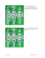
The Instrument 4 hardware configuration
jumpers are JP18, JP12, JP15 and JP17.
JP18 selects the function of pin 5 of the
INST 4 connector to be either a TriSonica
Trigger signal or the SCL (I2C Clock)
JP12 and JP15 change the serial port
configuration between EIA232 and UART
signaling levels.
JP17 selects the voltage applied to the
Instrument 4 connector: 3.3V, 5V, or 12V.
The defaults are SCL, EIA232, and 5V, as
shown in Figure 25Figure 25.
Analog and Digital Connector Hardware Configurations
Voltage output configuration is available for Analog and Digital 1 & 2 connectors.
The AD1 connector voltage jumper is JP1, and the AD2 connector voltage jumper is JP2.
These jumpers select between 5V and 3.3V.
The default is 5V.
GPS and Radio Connector Hardware Configurations
Voltage output configuration is available for the GPS and Radio connectors.
The GPS connector voltage jumper is JP9, and the Radio connector voltage jumper is JP10.
These jumpers select between 5V and 3.3V.
The default is 5V.
Circuit Board Modification
Modification to these jumpers must be done only by a skilled electronics technician.
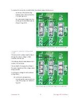
Changing a Two-Position Jumper
The configuration is changed by cutting the default jumper trace and soldering a bridge across two
pads of the jumper to change the connections.
Figure 25: Instrument 4 Hardware Configuration
Содержание Data Logger 422
Страница 1: ...Data Logger 422 User Manual...
Страница 8: ...Anemoment LLC 6 Data Logger 422 User Manual...
Страница 16: ...Anemoment LLC 14 Data Logger 422 User Manual...
Страница 52: ...Anemoment LLC 50 Data Logger 422 User Manual...


