INSTALLATION
SECTION 3
FUEL SUPPLY
19
1
2
5
9
7
3
8
6
4
H
P
H
1
10
7
6
9
8
3
4
7
1
10
H
3
6
4
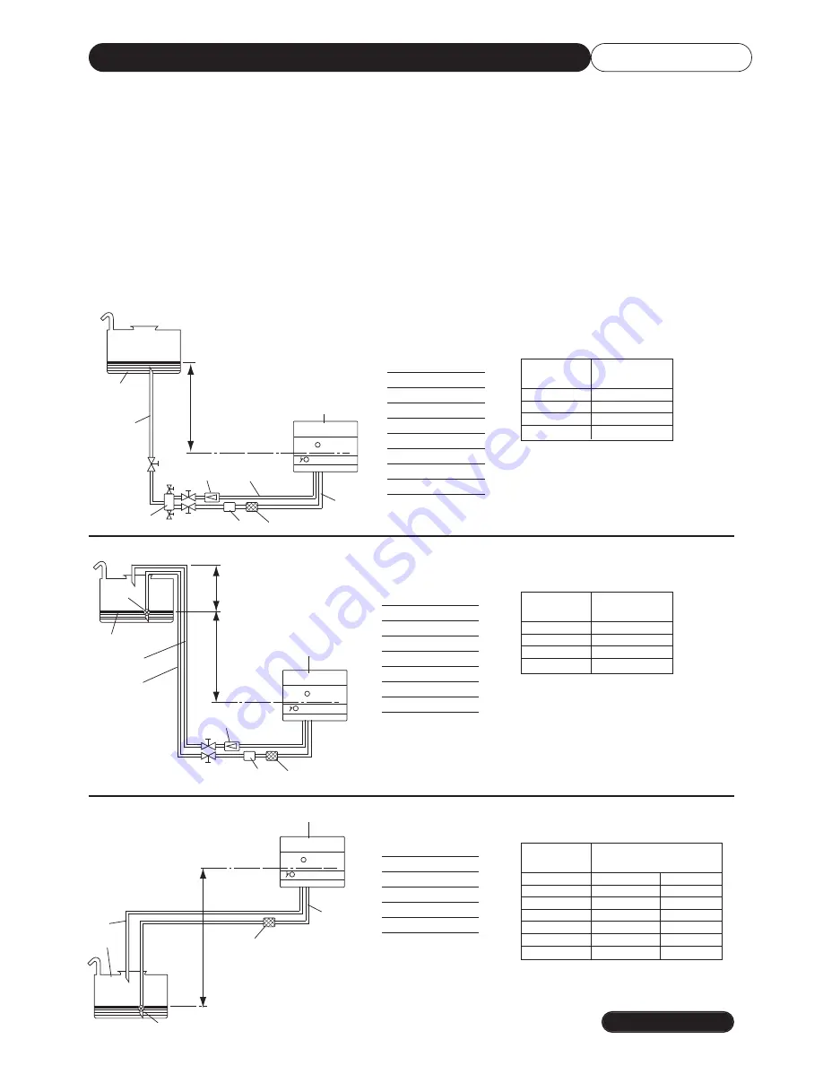
TYPICAL GRAVITY FROM THE BOTTOM OF OIL TANK
TYPICAL GRAVITY FEED OVER THE TOP OF OIL TANK
TYPICAL SUCTION FEED
1 Oil tank
2 Feed line
3 Filter
4 Burner
5 Degasifier
6 Suction line
7 Return line
8 Fire valve
9 Non return valve
H
Total meters
meters
Ø i. 10mm
1
30
2
35
3
40
4
45
H
Total meters
meters
Ø i. 10mm
1
30
2
35
3
40
4
45
1 Oil tank
3 Filter
4 Burner
6 Suction line
7 Return line
8 Fire valve
9 Non return valve
10 Foot valve
1 Oil tank
3 Filter
4 Burner
6 Suction line
7 Return line
10 Foot valve
H = Measurement between minimum oil level and pump axis
L
= Max. length of suction line, including vertical lifts. For each bend of valve deduct 0,25m.
Ø = Internal diameter of pipe
H
Total meters
meters
Ø i. 10mm Ø i. 12mm
0,5
26
54
1
24
47
1,5
18
38
2
14
30
2,5
10
23
3
6
15
3,5
-
7
A fire valve and filter must be fitted in the fuel supply to the burner. (Not Supplied).
Current standards state that the "BIO-FUEL" has a blend of between 7% and 10%.
If a higher blend is being used then the burner manufacturer
MUST
be contacted for additional guidance.
Use either Kerosene Class C2 (BS2869) or Gas Oil Class D (BS2869). NO OTHER FUEL SHOULD BE USED.
Schematic representations of the fuel supply are shown below. It is suggested where possible a gravity feed is used.
Should a negative head system be employed, see typical example below.
MATERIALS AND JOINTING
All materials including the fuel storage tank, fuel supply pipe and jointing materials mustcomply fully with the
requirements in BS5410.
SITING OF FUEL STORAGE TANK
The siting of the fuel storage tank must fully comply with the requirements in BS5410.


