background image


Page 4-1 

CHAPTER 4: SETUP MENU DESCRIPTIONS AND PROCEDURES 


4.1  SETUP MENU DESCRIPTIONS 


This section provides more detailed descriptions of the selections found in the Setup Menu Chart. 
Factory-set defaults are shown in bold with a checkmark (

). 


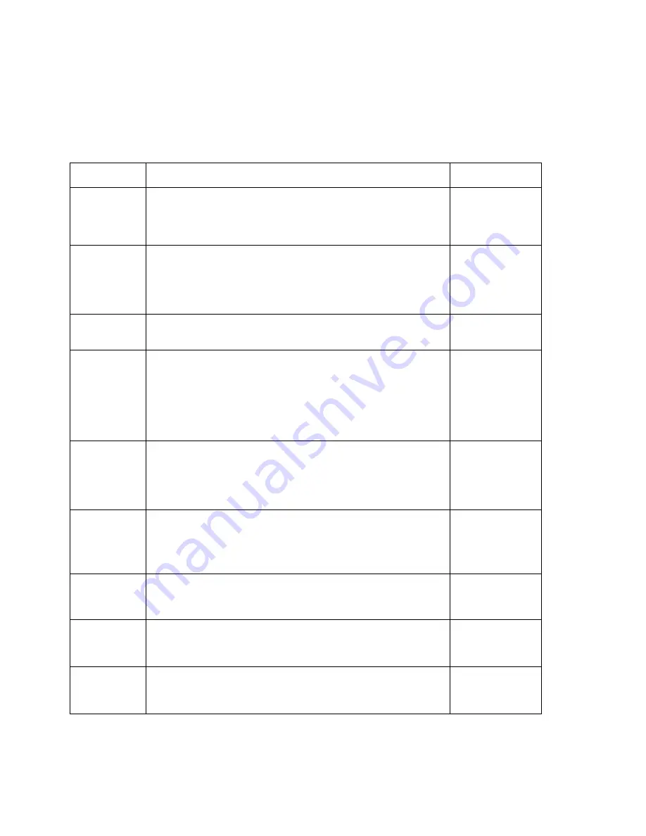
NAME/CODE DESCRIPTION  CODE/VALUE 

F1


Graduations 

Specifies number of full-scale graduations. Value should be consis-
tent with legal requirements and environmental limits on the useful 
system resolution. Pressing the 

ZERO

 key to scroll down one level 

begins the sequence. 

100 - 50000 

400


F3


Zero Track 
Band


Selects the range within which the scale will automatically zero. Note 
that the scale must be in standstill to automatically zero. Selections 
are in Display Divisions. 

0d


0.5d 
1d 

3d


5d 

F4


Zero Range


Selects the range within which the scale may be zeroed. Note that the 
indicator must be in standstill to zero the scale. 

100%


1.9% 

F5


Motion Band


Sets the level at which motion is detected by comparing the present 
display update with the previous one. If motion is not detected for two 
seconds or more, scale is in standstill and can process a Print or Zero 
command. Maximum value varies depending on local regulations. 

1d 

3d


5d 
10d 
15 d        20d 
30d         40d 
50d 

F6


Digital Filter


Averages weight readings to produce higher stability. The higher the 
filter setting, the greater the stability. 

0          1 
2          3


4          5 
6          7 

8


F7


Overload Limit


Selects the desired formula which determines the point at which the 
indicator shows overload. All selections are based on the primary unit 
selected in F8. 

"FS" = Full scale in primary units. 

FS 

FS + 2%


FS + 1d 
FS + 9d 

F8


Calib. Unit


Selects the primary base unit to be used in the calibration process. 
Also the default unit for normal operation. 
"1" = primary unit is lb.                       "2" = primary unit is in kg. 

1


F9


Display 
Divisions 

Determines the desired weight increments. Value should be consis-
tent with legal requirements.  


5


F10 

Decimal Pt.


Determines location of the decimal point.  

0               

0.0


0.00        0.000 
0.0000         00 


Visit www.balances.com Your Authorized A&D Dealer

Содержание U0-200

Страница 1: ...5 2005 A D Weighing Contents subject to change without notice A D Weighing 1555 McCandless Drive Milpitas CA 95131 Tel 800 726 3364 Fax 408 263 0119 E mail scales andweighing com Web www andweighing c...

Страница 2: ...in a commercial environment This equipment generates uses and can radiate radio frequency energy and if not installed and used in accordance with the instructions manual may cause harmful interference...

Страница 3: ...otes on the Setup Menu 3 2 3 2 4 Exiting the Setup 3 2 3 3 User A Menu 3 3 3 3 1 Entering the User Menu 3 3 3 3 2 Navigating in the User Menu 3 3 3 3 3 Notes on the User Menu 3 4 3 3 4 Exiting the Use...

Страница 4: ...on Value F19 6 3 6 6 Key in Span Calibration Value F20 6 3 Chapter 7 Operation 7 1 7 1 Display 7 1 7 1 1 Liquid Crystal Display LCD 7 1 7 2 Keyboard 7 2 7 2 1 Function Keys 7 2 7 3 General Scale Opera...

Страница 5: ...ntered via the front panel keys including calibration The UO 200 is powered with six C cell alkaline batteries not included An AC adapter option is also available Prior to using the UO 200 please read...

Страница 6: ...ector into the load cell port on the rear panel of the indicator 2 1 2 CONNECTING THE POWER SUPPLY 1 Obtain six 6 alkaline C UM 2 batteries and install them into the battery compartment located at the...

Страница 7: ...opposite position See Chapter 2 for location of the Setup Calibration Switch 3 Power on the UO 200 The indicator shows F 1 to indicate that you are in Setup Menu mode 3 2 3 NAVIGATING IN THE SETUP MEN...

Страница 8: ...o begin Figure 3 2 Setup Menu Chart 3 2 4 NOTES ON THE SETUP MENU 1 There is also an F21 sub menu present that is for FACTORY USE ONLY 2 Detailed descriptions of the setup menu parameters can be found...

Страница 9: ...Chart shown in Figure 3 4 on the following page 1 To move to a new A heading use the TARE left or ON PRINT right key to move right or left in the User Menu Chart 2 To move to the selection level pres...

Страница 10: ...Enable 0 1 A16 Time Format 0 1 A17 Time Entry A18 Data Enable 0 1 A19 Date Format 0 1 A20 Date Entry Press ZERO key to begin Press ZERO key to begin 1 2 Figure 3 4 User Menu Chart 3 3 3 NOTES ON THE U...

Страница 11: ...evel at which motion is detected by comparing the present display update with the previous one If motion is not detected for two seconds or more scale is in standstill and can process a Print or Zero...

Страница 12: ...1 Factory Reset This sub menu will reset all parameters in the F and A menu to the default settings USE WITH CAUTION Press the ZERO key twice to exe cute 4 2 SETUP MENU PROCEDURES This section provide...

Страница 13: ...down one level begins the sequence 0 Disabled Always ON 0 30 2 5 2 USER MENU PROCEDURES USER MODE KEY FUNCTIONS ZERO GROSS NET TARE PRINT SET UNITS Figure 5 1 User Menu Key Assignments 5 2 1 Auto Powe...

Страница 14: ...oll down once using the ZERO key to enter zero calibration menu The display will momentarily show C 0 followed by a value This value is the internal A D count and can prove useful when trying to troub...

Страница 15: ...in weight is smaller than 1 of the full capacity of the scale Change the calibration test weight or check the input data Err2 The internal resolution of the scale is not high enough to accept the cal...

Страница 16: ...e obtained from a successful F17 calibration procedure must be used 1 While in the Setup mode scroll to F 20 then scroll down once using the ZERO OFF key The indicator will prompt you to enter the inf...

Страница 17: ...t is active when ever the displayed weight is within 0 25 divisions of true zero N Indicates that the indicator is displaying net weight G Indicates that the indicator is displaying gross weight T Ind...

Страница 18: ...ndicator between Gross weight and Net weight only if a Tare has been established Tare This key is used to establish a Tare provided the following conditions are met 1 The indicator is not at or below...

Страница 19: ...y press the ZERO OFF key to obtain a weight reading of zero 3 Place the empty container on the scale s platter and allow the weight indication to stabi lize 4 Press the TARE key The display shows zero...

Страница 20: ...rage in EEPROM Excitation Voltage 3 3 VDC 4 x 350 load cells DIGITAL SPECIFICATIONS Microcontroller TI MSP430F447 Program Memory 32K x 8 internal to C SRAM 1Kx 8 internal to C EEPROM 256 x 8 external...

Страница 21: ...ration Mode F17 Keyed in weight value is less than 1 of full scale capacity Use a larger test weight or check keyed in value Err 2 Span Calibration Mode F17 There is not enough load cell signal to pro...

Отзывы: