background image

13

12

Load Sharing Option

The Load Sharing Option allows you to connect two or more units in parallel, allowing them 

to share in supplying current to the load(s).  Connecting units together this way has many 

advantages, it reduces stress on each individual power supply and in addition, the load can 

draw greater current than from a single unit. 
Units built with this option are equipped with special output isolation diodes on the output 

terminals.  You can check if your unit has these diodes by using an ohmmeter to measure the 

resistance between the two positive output terminals.
•   If the diodes are present, the terminals will measure as not connected.

•   If the diodes are NOT present, the terminals will measure as a short circuit. 

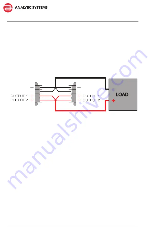
To set up load sharing:

1.  Connect a length of #12 AWG RED wire to each positive output terminal of each unit.
2.  Connect all the positive wires to a distribution bus or join them together at a common point. 
3.  Connect the distribution bus or common point to the load using an appropriate gauge of 

wire for the total output current capability of all the supplies running in parallel. 

4.  Repeat Steps 1-3 for the negative output terminals using the same gauges of BLACK wire.
5.  The units should now load share. 
6.  You can confirm this by checking the output terminals using an ammeter or or by checking 

the integrated voltmeter/ammeter if the unit is built with that option.

Unit #1

Unit #2

TIP:


The Output Voltage Adjust can also be used to adjust the output current.

A slight difference in the output current between the units is negligible. However, if this isn’t the 

case, the current can be adjusted using the Output Voltage Adjust potentiometer. Increasing the 

output voltage decreases the output current and vice versa. 

Содержание PWS1005W

Страница 1: ...128 River Way Delta B C V4G 1K5 Canada T 604 946 9981 F 604 946 9983 TF 800 668 3884 US CANADA www analyticsystems com An ISO9001 Registered Company Battery Chargers Inverters Power Supplies Voltage C...

Страница 2: ...2 Copyright 2005 2020 Analytic Systems Ware 1993 Ltd Revised Feb 24 2020...

Страница 3: ...per installation can result in the risk of electric shock WARNING Do not use this power supply to charge a battery It does not have the necessary circuitry on the output to prevent it from overchargin...

Страница 4: ...oduct Warnings and Advisories Table of Contents Introduction Box Contents Main Parts Operation Output Fuse Replacement Installation Troubleshooting Product Options Specifications Warranty Copyright 20...

Страница 5: ...put ripple to levels previously only available from bulky inefficient linear power supplies In addition multiple stages of filtering on the input and output reduce radiated and conducted noise to very...

Страница 6: ...itive Red and Negative Black encased in a sealcon gland 2 LED Operational Indicators 3 Power Switch 4 AC Input Connection 3 05m 10 00ft P3x14AWG power cord ending in a NEMA 5 15 125VAC plug encased in...

Страница 7: ...lowing green indicating the power supply is supplying the load TO TURN THE UNIT OFF 1 Move the Power Switch to the OFF position and wait for the POWER LED to stop glowing 2 Once all the LEDs are off i...

Страница 8: ...en Yellow AC Ground Wire color Polarity Black DC Output Negative Red DC Output Positive This unit s maximum continuous output current is 40A When connecting devices to the power supply ensure total co...

Страница 9: ...e front panel to the unit chassis 2 Gently wiggle the front panel to unplug it from the main circuit board The output fuses are mounted in fuse holders close to the output cable or connector 3 Remove...

Страница 10: ...ch device connected to the power supply does not exceed the unit s continuous output current See Specifications for more details UNDER V INPUT The AC input voltage is too low for proper operation Fix...

Страница 11: ...model 27 2V 1A Charger In Out Main PCB DC Output 28V Batt Batt OP OP 24V Battery To Load The Battery Backup Option allows you to connect a battery to the output of your unit to serve as a backup powe...

Страница 12: ...f 12 AWG RED wire to each positive output terminal of each unit 2 Connect all the positive wires to a distribution bus or join them together at a common point 3 Connect the distribution bus or common...

Страница 13: ...2 VDC 36 3 VDC 40 8 VDC 54 4 VDC 72 5 VDC Overvoltage Protection Crowbar 17 0 0 5V 34 0 1 0V 45 0 1 5V 51 0 1 5V 68 0 2 0V 90 0 2 5V Continuous Amps 80 A 40 A 30 A 27A 20 A 15 A Peak Amps 120 A 66 A 5...

Страница 14: ...to 55 C maximum output Derate Linearly 2 5 per C from 55 C Storage Temperature 40 C to 100 C Humidity 0 95 Relative Humidity non condensing and standard conformal coating Ingress Protection IP66 Dust...

Страница 15: ...ng will incur additional charges and are the responsibility of the Purchaser 6 Analytic Systems reserves the right to void the warranty if a Labels identification marks or serial numbers are removed o...

Страница 16: ...s com support warranty registration DESIGNED AND MANUFACTURED BY 800 668 3884 604 946 9983 Support analyticsystems com www AnalyticSystems com 8128 River Way Delta BC V4G 1K5 Canada Battery Chargers I...

Отзывы: