EVAL-ADAU1467Z
UG-1134
Rev. A (Draft) | Page 23 of 55
The
S/PDIF receiver accepts signals with sample
rates between 18 kHz and 192 kHz. Because the incoming signal
is asynchronous to the system sample rate, an asynchronous
sample rate converter (ASRC) must be used to convert the
sample rate of the incoming signal. Optionally, the
core
can be configured to start processing audio samples based on
the sample rate of the incoming S/PDIF receiver signal, meaning
that no ASRC is required. However, using an ASRC is strongly
recommended for performance and reliability reasons.
The
S/PDIF transmitter typically transmits signals
from the DSP core, meaning that the sample rate of the audio
coming out of the S/PDIF transmitter on the EVAL-ADAU1467Z is
typically 44.1 kHz or 48 kHz. Optionally, the S/PDIF transmitter
can be configured in a pass through mode, where it simply
transmits a copy of the signal directly from the receiver.
Both the S/PDIF receiver and transmitter carry two channels of
uncompressed audio.
Using S/PDIF in a SigmaStudio Project
To add an S/PDIF input and output to the project in
take the following steps:
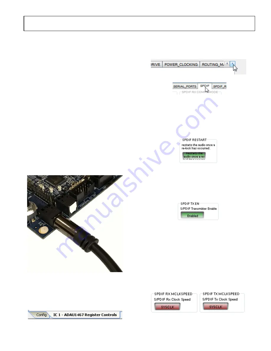
1.
Connect an S/PDIF source to the EVAL-ADAU1467Z
evaluation board by using a standard TOSLINK optical
cable and connecting it to the S/PDIF receiver connector,
U2 (see Figure 59).
Figure 59. Photograph of the Optical S/PDIF Input Connection
2.
Configure the S/PDIF input and output by modifying the
registers as follows:
a.
Click the
Hardware Configuration
tab, then click the
IC 1 - ADAU1467 Register Controls
tab at the
bottom of the window (see Figure 60).
Figure 60.
IC 1 – ADAU1467 Register Controls
Tab
b.
To access the
SPDIF
tab, click the right arrow to scroll
(see Figure 61).Then, click the
SPDIF
tab (see Figure 62).
There are several register control tabs listed across the
top of the window.
Figure 61. Using the Register Tab Scroll Button
Figure 62. Selecting the
SPDIF
Tab
c.
Enable the SPDIF_RESTART register by clicking
Do
not restart the audio once a re-lock has occurred
in
the
SPDIF RESTART
box. When this button is clicked,
the text displayed on the button changes to
Restarts
the audio once a re-lock has occurred
and the button
color changes from red to green (see Figure 63).
Figure 63. Activating the SPDIF_RESTART Register
d.
To activate the S/PDIF interface, click the
Disabled
button in the
SPDIF TX EN
box. When this button is
clicked, the text displayed on the button changes to
Enabled
and the button color changes from red to
green (see Figure 64).
Figure 64. Activating the SPDIF_TX_EN Register
e.
To enable the S/PDIF receiver to operate at a sample
rate up to 192 kHz, click
SYSCLKDIV2
in the
SPDIF
RX MCLKSPEED
box. When this button is clicked,
the text changes to
SYSCLK
and the button color
changes from green to red in the
SPDIF TX
MCLKSPEED
box. To enable the S/PDIF transmitter
to operate at a sample rate up to 192 kHz, click
SYSCLKDIV2
in the
SPDIF RX MCLKSPEED
box.
When this button is clicked, the text changes to
SYSCLK
and the button color changes from green to red in the
SPDIF TX MCLKSPEED
box (see Figure 65).
Figure 65. Setting the Maximum Sample Rate of the S/PDIF Receiver and
Transmitter
15786-
035
15786-
036
15786-
037
15789-
038
15786-
039
15786-
040
15786-
041
DRAFT
Содержание SigmaDSP ADAU1463
Страница 44: ...UG 1134 EVAL ADAU1467Z Rev A Draft Page 44 of 55 Figure 110 EVAL ADAU1467ZLayout Top Copper D R A F T...
Страница 45: ...EVAL ADAU1467Z UG 1134 Rev A Draft Page 45 of 55 Figure 111 EVAL ADAU1467Z Layout Layer 2 Ground D R A F T...
Страница 47: ...EVAL ADAU1467Z UG 1134 Rev A Draft Page 47 of 55 Figure 113 EVAL ADAU1467Z Layout Layer 4 Power D R A F T...
Страница 48: ...UG 1134 EVAL ADAU1467Z Rev A Draft Page 48 of 55 Figure 114 EVAL ADAU1467Z Layout Layer 5 Ground D R A F T...
Страница 49: ...EVAL ADAU1467Z UG 1134 Rev A Draft Page 49 of 55 Figure 115 EVAL ADAU1467Z Layout Bottom Copper D R A F T...


