background image

DEMO MANUAL SCP-LT8609S-BEVALZ 


Rev. 1 

QUICK START PROCEDURE 

Demonstration circuit SCP-LT8609S-BEVALZ is easy to 
set up to evaluate the performance of any SCP hard-
ware configuration. 

1. The SCP-LT8609S-BEVALZ ships with a default output 

voltage of 5V. To change the output voltage, see “Con-
figuration Settings” section, and modify the board ac-
cordingly. Be sure to check for open connections or sol-
der shorts after making any modifications. 

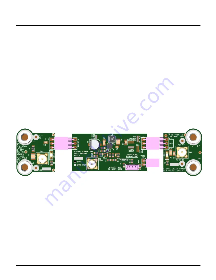
2. Connect  the  SCP-INPUT-EVALZ  and  SCP-OUTPUT-

EVALZ  boards  to  the  SCP-LT8609S-BEVALZ  (refer  to 
Figure  2)  and  connect  the  input  board  to  a  voltage 
source, V

SOURCE

. Connect the output board to a volt-

meter or dynamic load. Slowly raise the input voltage 
until the SCP-LT8609S-BEVALZ powers up into regula-
tion and sweep V

SOURCE

 through the desired range of 

operation. 

  NOTE: Make sure that the input voltage is always within 

spec. If using a dynamic load to measure output volt-
age, make sure the load is initially set to zero. 

3. Check for proper output voltage. The output should be 

regulated at the programmed value (±5%). 

4. Once  the  proper  output  voltage  is  established,  power 

off V

SOURCE 

and similarly test other boards in the SCP 

system until all elements have been individually verified 
prior to assembling into the final circuit configuration. 

  NOTE: When measuring the input or output voltage rip-

ple, use the optional SMA connector locations available 
on the input, output, 1 

´

 5, 1 

´

 2, and 5 

´

 1 breakout 

boards.  Avoid  using  the  test  point  connections  with 
long scope leads. 


Figure 2.


Proper Measurement Equipment Setup (Use SMA connectors for Measuring Input or Output Ripple) 

Содержание Linear ADI Power SCP-LT8609S-BEVALZ

Страница 1: ...HRUBRD EVALZ To properly evaluate SCP series demo boards you will need the SCP Configurator companion software SCP Configurator can help you choose the right board and to pology for your design Note that this Demo Manual does not cover details im portant to the operation and configuration regarding the LT8609S Please refer to the LT8609S datasheet for a com plete description of the part Design fil...

Страница 2: ... SCP LT8609S BEVALZ powers up into regula tion and sweep VSOURCE through the desired range of operation NOTE Make sure that the input voltage is always within spec If using a dynamic load to measure output volt age make sure the load is initially set to zero 3 Check for proper output voltage The output should be regulated at the programmed value 5 4 Once the proper output voltage is established po...

Страница 3: ... create a harness for this function use Molex part 0510650300 with crimp pin 50212 8000 To use an active run signal use a 1 00M for either pull up or pull down resistors R1 and R6 short R7 with 0W and use the drive signal from connector P1 If precision UVLO operation is desired program enable di vider R5 and R6 such that R6 is 10k to 100k nominal The LT8330 has an accurate 1 60V threshold which pl...

Страница 4: ...the user to program the switching fre quency fSW by a single resistor R2 The default operat ing frequency is 2 0MHz Note that changing the switching frequency may affect other parameters and likely will ne cessitate a change in inductor and compensation compo nent values Contact the SCP team for support if shifting the switching frequency greater than 10 Table5 Switching Frequency fSW vs Resistor ...

Страница 5: ... 2 54MM PITCH R A GOLD SULLINS PPPC031LGBN RC 12 1 P1 CONN PCB 3POS HEADER WIRE TO BRD WAFER ASSY STRAIGHT 2MM PITCH Note 1 MOLEX 53253 0370 13 1 R1 RES THICK FILM CHIP GENERAL PURPOSE YAGEO RC0805JR 071ML 14 1 R2 RES PRECISION THICK FILM CHIP PANASONIC ERJ 6ENF1822V 15 1 R3 RES PRECISION THICK FILM CHIP PANASONIC ERJ 3EKF4992V 16 1 R4 RES PRECISION THICK FILM CHIP PANASONIC ERJ 6ENF1004V 17 1 R5 ...

Страница 6: ...33 VIOC VO GND RUN V VNEG VNEG SYNC PG VO VNEG VIOC GND VO VO VNEG 14 PAD 8 11 3 2 1 5 1 2 3 4 1 2 3 1 2 1 2 1 3 12 20 18 13 3 4 5 6 16 2 9 10 15 7 17 19 1 EPAD NC NC NC NC SYNC TR SS GND FB PG EN UV VIN VIN GND NC SW SW GND GND VCC RT D THIS DRA WING IS THE PROPE RTY OF ANALOG DE VICES INC IN P ART OR USE D I N FURNISHING INFORMATION TO OTHE RS OR FOR ANY OTHE R PURPOSE DETRIMENTAL TO THE INTERES...

Страница 7: ...nge without notice No license is granted by implication or otherwise under any patent or patent rights of Analog Devices Information furnished by Analog Devices is believed to be accurate and reliable However no responsibility is assumed by Analog Devices for its use nor for any infringements of patents or other rights of third parties that may result from its use Specifications subject to change ...

Страница 8: ...not disclose or transfer any portion of the Evaluation Board to any other party for any reason Upon discontinuation of use of the Evaluation Board or termination of this Agreement Customer agrees to promptly return the Evaluation Board to ADI ADDITIONAL RESTRICTIONS Customer may not disassemble decompile or reverse engineer chips on the Evaluation Board Customer shall inform ADI of any occurred da...

Отзывы: