UG-1926
Rev. 0 | Page 12 of 20
25
84
4-
0
08
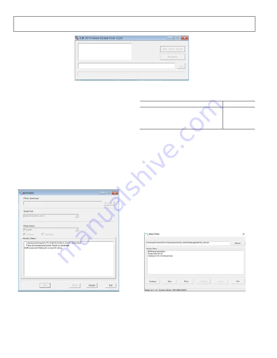
Figure 18. GUI for Updating the SUB-20 Firmware
2.
For Windows® 10, Figure 18 may open automatically to
update the SUB-20 adapter without having to double click
the
SUB-20 firmware updater.exe
file. Click the
Update
button. For Windows 7 and earlier versions, users may not
need to update the SUB-20 adapter.
3.
After the adapter finishes updating, connect the pins on the
SUB-20 board to the pins on the EVAL-ADUCM420QSP1Z
as described in Table 5.
4.
On the SUB-20 board, ensure that Pin J7 is set to 3.3 V,
Pin JP1 to Pin JP4 and Pin JP5 are set to connect Header
Pin 1 to Header Pin 2, and Pin JP6 is set to connect Header
Pin 2 to Header Pin 3.
5.
Connect the USB cable from the PC to the SUB-20 board and
run
C:\ADuCM420…\SoftwareTools\MDIOWSD\
MDIOWSD.exe
. The GUI window then opens, as shown
6.
Click the
Browse
button (see Figure 19), and navigate to
the desired code to download.
2584
4-
00
9
Figure 19.
MDIOWSD
GUI
7.
To download the code, select
Program and Verify
from
the Flash Action
box, click
Start
, and follow the
instructions listed on the GUI.
Table 5. SUB-20 to EVAL-ADUCM420QSP1Z Pin
Connection Guide
EVAL-ADUCM420QSP1Z Pins on P4
SUB-20 Pins
DGND J6-10
1.2V
J6-9
MDIO J6-7
MCK J6-1
For more information about flash block switching and the
MDIO, refer to the
ADuCM420 hardware reference manual
EVALUATING THE I
2
C DOWNLOAD MODE
The I
2
C downloader can be extracted from the installer on the
ftp://ftp.analog.com/pub/microconverter/ADuCM420
website.
Use the I
2
C downloader with the
M12CFTWSD
software to
download the hexadecimal files. Use the on-board FTDI chip to
interface with the device. The FTDI chip allows connectivity
between the EVAL-ADUCM420QSP1Z board and the PC via
the
MI2CFTWSD
software tool. When the downloader is
extracted, follow these steps:
1.
On the EVAL-ADUCM420QSP1Z, ensure JP7, JP8, JP9,
and JP10 are shorted to use the on-board FTDI chip.
2.
Open the
MI2CFTWSD
folder, and double click
MI2CFTWSD.exe
.
3.
The GUI opens, as shown in Figure 20.
25
84
4
-1
17
Figure 20.
MI2CFTWSD
GUI


