EVAL-ADuC7026 User Guide
UG-669
Rev. B | Page 5 of 16
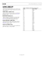
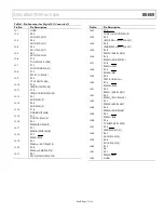
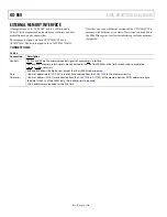
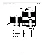
DIP SWITCH LINK OPTIONS
S1-1 V
REF
Function
Connects the output of the 2.5 V external reference (
)
to the V
REF
Use
Slide S1-1 to the on position to connect the external reference
to the
Slide S1-1 to the off position to use the internal 2.5 V reference
or a different external reference on the V
REF
pin of Header J3.
S1-2 V
OCM
Function
Connects 1.67 V to the V
OCM
. No extra
dc voltage is required on the board to use the ADC in
differential mode.
Use
Slide S1-2 to the on position to connect V
OCM
of the differential
amplifier to the 1.67 V divided output of the
reference.
Slide S1-2 to the off position to use a different voltage for V
OCM
by connecting a dc voltage to the V
OCM
pin of Header J3. Note
that the V
OCM
value is dependent on the reference value, as
shown in Table 1.
Table 1. V
OCM
Range
V
REF
V
OCM
Minimum
V
OCM
Maximum
2.5 V
1.25 V
2.05 V
2.048 V
1.024 V
2.276 V
1.25 V
0.75 V
2.55 V
S1-3 POT
Function
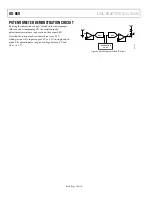
Connects the potentiometer output to ADC0. This input is
buffered by an
. This is for demonstration purposes.
Use
Slide S1-3 to the on position to connect the potentiometer to
the op amp of the ADC0 input channel.
Slide S1-3 to the off position to use the ADC0 input on Header J3.
S1-4 ADC3
Function
Brings out ADC3 (Pin 80) on Header J3.
Use
Slide S1-4 to the on position to connect ADC3 of Header J3
directly to the ADC3 pin (Pin 80) of the
Slide S1-4 to the off position to disconnect ADC3 of Header J3
from the ADC3 pin (Pin 80) of the
S1-5 VIN−
Function
Connects the −OUT pin of the single-ended to differential op
amp (
) to ADC3. S1-5 and S1-6 must be used together.
When VIN− is in the on position, VIN+ must also be in the on
position to use the differential op amp on Channel ADC3 and
Channel ADC4.
Use
Slide S1-5 to the on position to connect −OUT of the
to ADC3.
Slide S1-5 to the off position to use ADC3 without the
S1-6 VIN+
Function
Connects the +OUT pin of the single-ended to differential op
amp (
) to ADC4. When VIN+ is in the on position,
VIN− must also be in the on position to use the differential op
amp on Channel ADC3 and Channel ADC4.
Use
Slide S1-6 to the on position to cOUT of the
to ADC4.
Slide S1-6 to the off position to use ADC4 without the
S1-7 ADC4
Use
Slide S1-7 to the on position to connect ADC4 of Header J3
directly to the ADC4 pin (Pin 1) of the
Slide S1-7 to the off position to disconnect ADC4 of Header J3
from the ADC4 pin (Pin 1) of the
S1-8 LED
Function
Connects the DAC1 output to the green LED of the
demonstration circuit, D1.
Use
Slide S1-8 to the on position to connect the DAC1 output to D1.
Slide S1-8 to the off position to use the DAC1 output on
Header J3.


