background image

UG-1256 

EVAL-ADPD188GGZ

 User Guide 


Rev. 0 | Page 4 of 9 

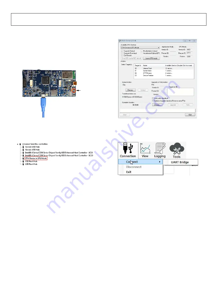
If the firmware must be updated, take the following steps: 

1.


Download and install the latest DfuSe USB device 
firmware upgrade software. 

2.


Plug in a microUSB cable between th

EVAL-

ADPDUCZ

 and the PC with the power to the 

EVAL-

ADPDUCZ

 turned off (see Figure 6)

3.


Press and hold the 

BOOT0

 button, and switch the power 

switch to the 

ON

 position (see Figure 6). 

BOOT0
BUTTON

16617-

006


Figure 6. MicroUSB Connection and BOOT0 Button Used When Upgrading 

Firmware 

4.


Go to 

Device Manager

 > 

Universal Serial Bus 

controllers

 and wait until the PC detects 

STM Device 

in DFU Mode 

(see Figure 7). 

16617-

007


Figure 7. 

STM Device in DFU Mode

 Displayed 

5.


Release the 

BOOT0 

button. 

6.


Open the 

DfuSe Demo

 by going to 

Start

 > 

All 

Programs

 > 

STMicroelectronics 

DfuSe

 > 

DfuSe 

Demo

. Figure 8 shows the 

DfuSe 

demo settings at 

startup. 

7.


In the 

Upgrade or Verify Action 

section, click 

Choose

and select the 

Adpd_M4_uC.dfu

 file from the 

Firmware


folder of the downloaded software package. 

8.


Click 

Upgrade

 and follow the prompts to upgrade the 

firmware of th

EVAL-ADPDUCZ

 microcontroller 

board. 

After the firmware is updated, connection to the Applications 

Wavetool can be completed. 

16617-

008


Figure 8. 

DfuSe Demo 

Settings 

USB UART CONNECTION 

To establish the connection, follow the menu path 

Connection 

Connect

 > 

UART Bridge

16617-

009


Figure 9. UART Connect 

Select the proper COM port to connect the Applications Wavetool 
to the device. If connection via Bluetooth® is required, or if there are 
any other connection issues, refer to the Applications Wavetool 

user guide that is provided in the software package download. 


Содержание EVAL-ADN469xEFDEBZ

Страница 1: ...ckage GENERAL DESCRIPTION The EVAL ADPD188GGZ evaluation board provides users with a simple means of evaluating the ADPD188GG optical module for vital signs monitoring applications The evaluation system includes the Applications Wavetool graphical user interface GUI that provides users with low level and high level configurability real time frequency and time domain analysis and user datagram prot...

Страница 2: ...alling the Applications Wavetool 3 Connecting the EVAL ADPDUCZ Microcontroller Board and the EVAL ADPD188GGZ Evaluation Board 3 Checking the USB Serial Connection in Windows 3 Running the Applications Wavetool 3 Instructions to Load the Firmware 3 USB UART Connection 4 Acquiring Data 5 Selecting the Proper View 5 Load Configuration 5 Optimizing and Running the ADPD188GG 6 Evaluation Board Schemati...

Страница 3: ...rocontroller board is on SWITCH TO ON 16617 003 Figure 3 Connect the EVAL ADPDUCZ to the EVAL ADPD188GGZ CHECKING THE USB SERIAL CONNECTION IN WINDOWS Ensure that the COM port driver is installed correctly To verify proper installation go to Control Panel All Control Panel Items System Device Manager as shown in Figure 4 In this case the proper COM port selection is USB Serial Port COM16 The EVAL ...

Страница 4: ...pen the DfuSe Demo by going to Start All Programs STMicroelectronics DfuSe DfuSe Demo Figure 8 shows the DfuSe demo settings at startup 7 In the Upgrade or Verify Action section click Choose and select the Adpd_M4_uC dfu file from the Firmware folder of the downloaded software package 8 Click Upgrade and follow the prompts to upgrade the firmware of the EVAL ADPDUCZ microcontroller board After the...

Страница 5: ... a window that allows the user to run the ADPD188GG device and collect data see Figure 12 16617 010 Figure 10 Select ADPD Device LOAD CONFIGURATION In the upper right corner of the data view window click the ADPD Config button to open the ADPD Config view see Figure 11 Click Load DCFG to select a configuration file For PPG measurements select the ADPD188Normal dcfg configuration file 16617 011 Fig...

Страница 6: ...optimized for any set of conditions by manipulating LED drive currents transimpedance amplifier TIA gain and analog front end AFE timing or by using different operating modes that may be more optimal for a specific set of conditions for example using float mode for very low current transfer ratio CTR For information on optimization of the ADPD188GG refer to the ADPD188GG data sheet For functional ...

Страница 7: ...SPI2_CS0 P1_5 CONN2_SPI2_MOSI P1_3 SYS_HWRST VLDO2 5 CONN2_UART_TX CONN2_ADXL364_ADC CONN2_BPR0_TONE_P SPI2_CS1 P0_9 DF40HC 2 5 20DS 0 4V 51 1 3PIN_JUMPER R9 1µF CONN2_WAKE3 TMR2_OUT P2_1 AD8233MON_LOD AD8233MON_SDNN 0Ω 0Ω R8 DNI 12 10 DNI VLDO1 IOVDD 0Ω VLDO3 0Ω R10 DNI 0Ω 10µF 12 VDD_1 8V DNI C41 R4 0Ω CONN1_SPI1_MISO P1_8 CONN1_WAKE0 P0_15 VDD_3V 6 16 14 11 CONN1_SPI1_MOSI P1_7 CONN1_I2C_SCL P0...

Страница 8: ...UG 1256 EVAL ADPD188GGZ User Guide Rev 0 Page 8 of 9 16617 014 Figure 14 EVAL ADPD188GGZ Primary Layer 16617 015 Figure 15 EVAL ADPD188GGZ Secondary Layer ...

Страница 9: ...r party for any reason Upon discontinuation of use of the Evaluation Board or termination of this Agreement Customer agrees to promptly return the Evaluation Board to ADI ADDITIONAL RESTRICTIONS Customer may not disassemble decompile or reverse engineer chips on the Evaluation Board Customer shall inform ADI of any occurred damages or any modifications or alterations it makes to the Evaluation Boa...

Отзывы: