UG-1819
Rev. 0 | Page 9 of 24
Setting Up the System for Data Capture
After completing the steps in the Software Installation Procedures
section and the Evaluation Board Hardware section, set up the
system for data capture as follows:
1.
Allow the Found New Hardware wizard to run after
connecting the
board to the PC. If using Windows XP,
it may be necessary to search for the
drivers. Choose
to automatically search for the drivers for the
prompted by the operating system.
2.
Check that the EVAL-AD4114SDZ is connected to the PC
correctly using the Device Manager of the PC. Access the
Device Manager as follows:
a.
Right-click My Computer and then click Manage.
b.
A dialog box appears asking for permission to allow
the program to make changes to the PC. Click Yes.
c.
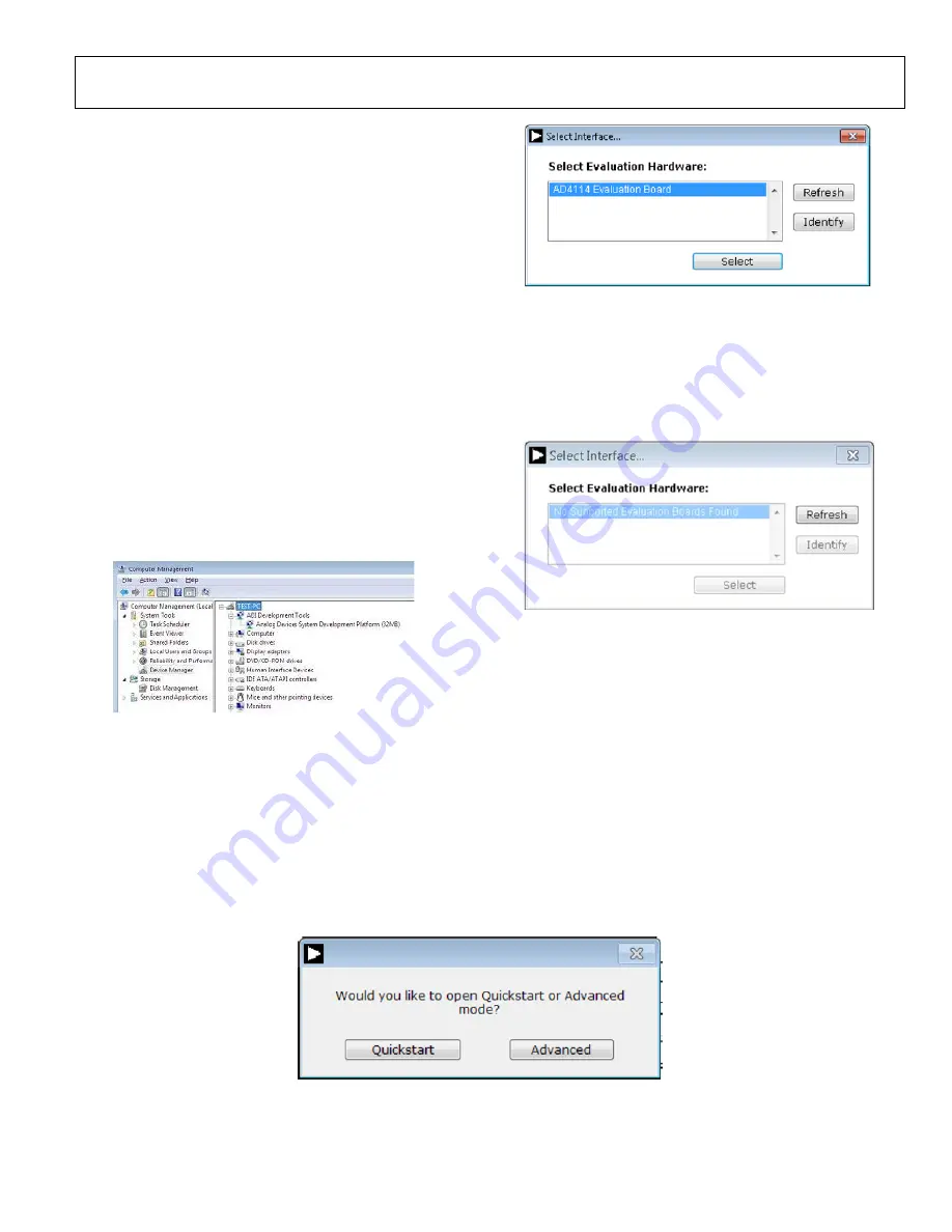
The Computer Management window appears. Click
Device Manager from the System Tools list (see
Figure 12).
d.
If the
board appears under ADI Development
Tools in the TEST PC nested list, the driver software has
installed and the
board is connected to the PC
correctly.
24002-
012
Figure 12. Checking if the
Board is Connected to the PC Correctly
Launching the Software
After completing the steps in the Setting Up the System for Data
Capture section, launch the
1.
From the Start menu, click Programs > Analog Devices >
AD411x Eval+ > AD411x Eval+.exe. The dialog box
shown in Figure 13 appears. Select AD4114 Evaluation
Board and the main window of the software shown in
Figure 16 appears.
24002-
013
Figure 13.
Evaluation Board Selection
2.
If the EVAL-AD4114SDZ is not connected to the USB port
via the
when the software is launched, the software
displays the dialog box shown in Figure 14. Connect the
EVAL-AD4114SDZ to the USB port of the PC, wait a few
seconds, then click Refresh, the dialog box shown in
Figure 13 then appears.
24002-
014
Figure 14. Evaluation Board Selection, No Board Connected
3.
The dialog box shown in in Figure 15 appears as a pop-up
over Figure 16. Quick start mode provides a simplified
version of the software that can be used as a starting point
for evaluating the
. This mode provides a graphical
user interface (GUI) for setting up inputs, as shown in
Figure 16, and allows the user to configure the device
further by using the blue configu buttons (Label 7
in Figure 16).
4.
Advanced mode can be used when more configurability of
the inputs is required. In this mode, the input GUI is not
available. However, the user has access to the Registers tab,
which provides full control of the
register map
(see Figure 17). When operating in advanced mode, the
user must consult the
data sheet.
24002-
015


