Analog Devices Blackfin Audio EZ-Extender Скачать руководство пользователя страница 36

3.3V

5V

3.3V

D

4

3

2

1

A

B

C

20 Cotton Road

Nashua, NH 03063

A

B

C

D

4

3

2

1

PH: 1-800-ANALOGD

C

Title

Size

Board No.

Date

Sheet

of

DEVICES

ANALOG

Rev

2.0

A0186-2003

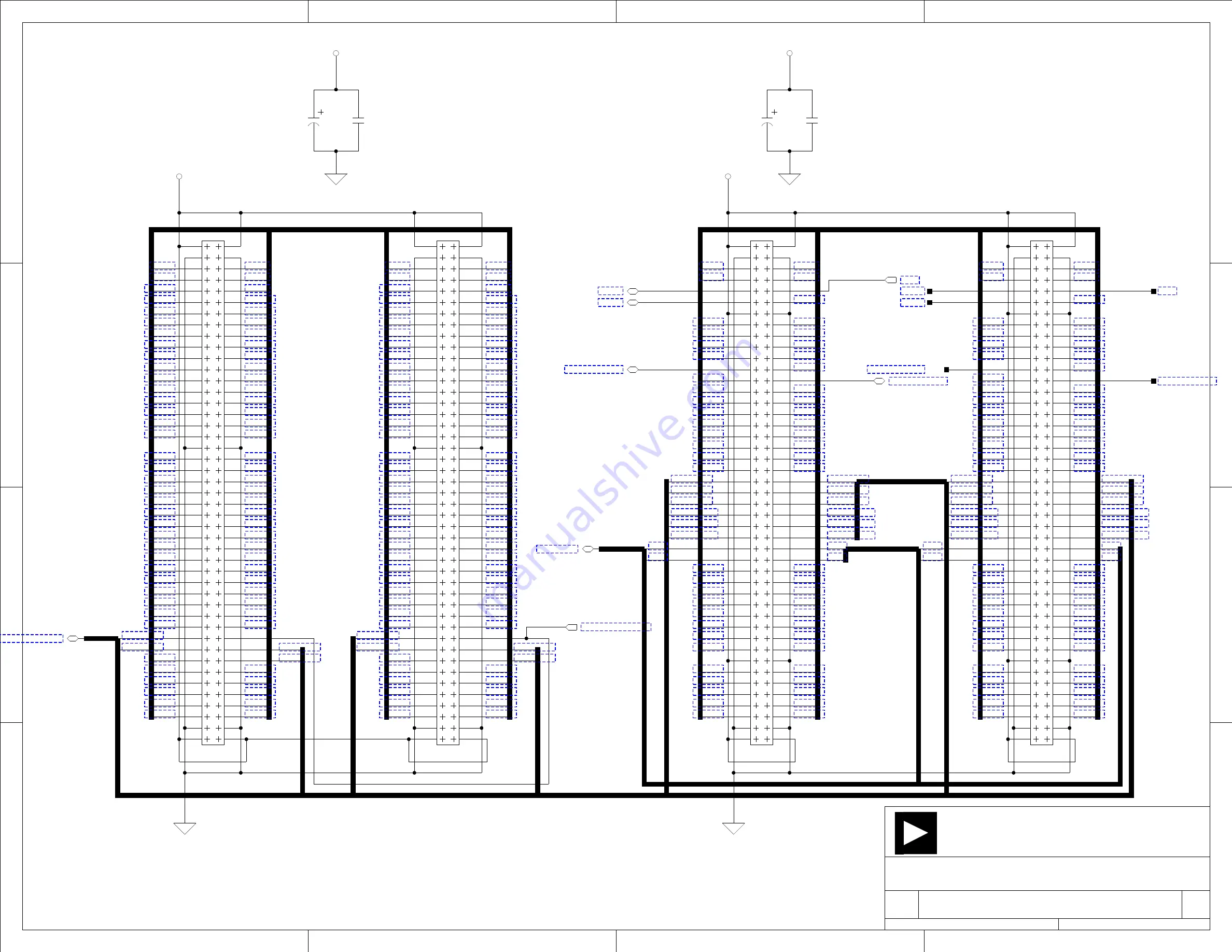
BLACKFIN EZ-EXTENDER

5V

Expanison Connector

P1

P2

Expanison Connector

(TMR1)

(TMR1)

(TMR2)

(TMR2)

EXPANSION INTERFACE (TYPE B)

4-24-2006_9:34

2

7

PPI0_SYNC2

PPI0_SYNC2

1

10

11

12

13

14

15

16

17

18

19

20

21

22

23

24

25

26

27

28

29

3

30

31

32

33

34

35

36

37

38

39

4

40

41

42

43

44

45

46

47

48

49

5

50

51

52

53

54

55

56

57

58

59

6

60

61

62

63

64

65

66

67

68

69

7

70

71

72

73

74

75

76

77

78

79

8

80

81

82

83

84

85

86

87

88

89

9

90

2

CON018

P2

1

10

11

12

13

14

15

16

17

18

19

20

21

22

23

24

25

26

27

28

29

3

30

31

32

33

34

35

36

37

38

39

4

40

41

42

43

44

45

46

47

48

49

5

50

51

52

53

54

55

56

57

58

59

6

60

61

62

63

64

65

66

67

68

69

7

70

71

72

73

74

75

76

77

78

79

8

80

81

82

83

84

85

86

87

88

89

9

90

2

P1

CON018

EXP_PPI0_CLK

PF[0:3]

PF0

PF2

PF3

PF1

PF0

PF2

PF3

PF1

0805

0.1UF

C4

10UF
B

CT2

0.1UF
0805

C17

B

10UF

CT1

SCK

MISO

MOSI

PPI0_SYNC1

PPI0_D2

PPI0_D0

PPI0_D3

PPI0_D1

PPI0_D[0:15]

PPI0_D3

PPI0_D1

PPI0_D5

PPI0_D4

PPI0_D14

PPI0_D12

PPI0_D10

PPI0_D8

PPI0_D6

PPI0_D7

PPI0_D9

PPI0_D11

PPI0_D15

PPI0_D4

PPI0_D6

PPI0_D8

PPI0_D10

PPI0_D12

PPI0_D14

PPI0_D15

PPI0_D5

PPI0_D7

PPI0_D9

PPI0_D11

PPI0_D13

PPI0_D0

PPI0_D2

PPI0_D13

P1_5

P1_6

P1_40

P1_70

P1_76

P1_86

P1_84

P1_82

P1_80

P1_78

P1_68

P1_66

P1_64

P1_62

P1_60

P1_58

P1_56

P1_54

P1_52

P1_50

P1_48

P1_46

P1_44

P1_42

P1_36

P1_34

P1_32

P1_30

P1_28

P1_26

P1_24

P1_22

P1_20

P1_18

P1_16

P1_14

P1_12

P1_10

P1_8

P1_39

P1_77

P1_85

P1_83

P1_81

P1_79

P1_69

P1_67

P1_65

P1_63

P1_61

P1_59

P1_57

P1_55

P1_53

P1_51

P1_49

P1_47

P1_45

P1_43

P1_41

P1_35

P1_33

P1_31

P1_29

P1_27

P1_25

P1_23

P1_21

P1_19

P1_17

P1_15

P1_13

P1_11

P1_9

P1_7

P1_[5:86]

P1_83

P1_81

P1_79

P1_77

P1_69

P1_67

P1_65

P1_63

P1_61

P1_59

P1_57

P1_51

P1_53

P1_49

P1_47

P1_45

P1_43

P1_41

P1_39

P1_35

P1_33

P1_31

P1_29

P1_27

P1_25

P1_23

P1_21

P1_19

P1_17

P1_15

P1_13

P1_11

P1_9

P1_5

P1_7

P1_55

P1_85

P1_8

P1_84

P1_86

P1_82

P1_80

P1_78

P1_76

P1_70

P1_68

P1_66

P1_64

P1_62

P1_60

P1_58

P1_56

P1_54

P1_52

P1_50

P1_48

P1_46

P1_44

P1_42

P1_40

P1_36

P1_34

P1_32

P1_30

P1_28

P1_26

P1_24

P1_22

P1_20

P1_18

P1_16

P1_14

P1_12

P1_10

P1_6

P2_[5:86]

P2_26

P2_86

P2_84

P2_82

P2_80

P2_78

P2_74

P2_72

P2_70

P2_68

P2_66

P2_64

P2_62

P2_60

P2_42

P2_40

P2_38

P2_36

P2_34

P2_32

P2_30

P2_28

P2_6

P2_8

P2_16

P2_18

P2_20

P2_22

P2_28

P2_30

P2_32

P2_34

P2_36

P2_38

P2_40

P2_60

P2_62

P2_64

P2_66

P2_68

P2_70

P2_72

P2_74

P2_78

P2_80

P2_82

P2_84

P2_86

P2_42

P2_26

P2_5

P2_7

P2_11

P2_15

P2_17

P2_19

P2_21

P2_23

P2_27

P2_29

P2_31

P2_33

P2_35

P2_37

P2_39

P2_41

P2_61

P2_63

P2_65

P2_67

P2_69

P2_71

P2_73

P2_77

P2_79

P2_81

P2_83

P2_85

P2_59

P2_85

P2_83

P2_81

P2_79

P2_77

P2_73

P2_71

P2_69

P2_67

P2_65

P2_63

P2_61

P2_59

P2_41

P2_39

P2_37

P2_35

P2_33

P2_31

P2_29

P2_27

P2_23

P2_21

P2_19

P2_17

P2_15

P2_11

P2_7

P2_5

P2_6

P2_8

P2_16

P2_18

P2_20

P2_22

EXPANSION CONNECTOR 1 AND 2

87

85

83

81

77

75

73

69

67

65

63

61

59

57

1

10

11

12

13

14

15

16

17

18

19

2

20

21

22

23

24

25

26

27

28

29

3

30

31

32

33

34

35

36

37

38

39

4

40

41

42

43

44

45

46

47

48

5

50

6

7

8

9

49

55

51

53

52

54

56

58

60

62

66

70

68

72

74

76

78

80

82

84

86

88

90

89

64

71

79

P4

CON017

45X2

DNP

MOSI

PPI0_SYNC1

MISO

SCK

87

85

83

81

77

75

73

69

67

65

63

61

59

57

1

10

11

12

13

14

15

16

17

18

19

2

20

21

22

23

24

25

26

27

28

29

3

30

31

32

33

34

35

36

37

38

39

4

40

41

42

43

44

45

46

47

48

5

50

6

7

8

9

49

55

51

53

52

54

56

58

60

62

66

70

68

72

74

76

78

80

82

84

86

88

90

89

64

71

79

DNP

45X2

CON017

P5

Содержание Blackfin Audio EZ-Extender

Страница 1: ...a Blackfin EZ Extender Manual Revision 4 1 July 2012 Part Number 82 000735 01 Analog Devices Inc One Technology Way Norwood Mass 02062 9106...

Страница 2: ...urate and reliable However no responsibility is assumed by Analog Devices for its use nor for any infringement of patents or other rights of third parties which may result from its use No license is g...

Страница 3: ...CE mark The Blackfin EZ Extender has been appended to Analog Devices Inc EMC Technical File EMC TF referenced DSPTOOLS1 dated December 21 1997 and was declared CE compliant by an appointed Notified B...

Страница 4: ......

Страница 5: ...ce ix Manual Contents x What s New in This Manual x Technical Support xi Supported Products xii Product Information xii Analog Devices Web Site xii EngineerZone xiii Related Documents xiv EZ EXTENDER...

Страница 6: ...ntrol Switch SW1 2 4 Clock Routing Switch SW2 2 5 General Frame Sync Routing Switch SW3 2 7 LCD Frame Sync Routing Switch SW4 2 8 MISO Disconnect Jumper P7 2 9 SMA Connector Clock Disconnect Jumper P1...

Страница 7: ...vironment The Blackfin EZ Extender is designed to be used in conjunction with the CrossCore Embedded Studio CCES and VisualDSP software development environments The development environment facilitates...

Страница 8: ...an LCD display device Moreover the extender broadens the range of the EZ KIT Lite applications by pro viding surface mounted SMT footprints for breadboard capabilities and access to all of the pins o...

Страница 9: ...Dimensions 5 in H x 5 in W Purpose of This Manual The Blackfin EZ Extender Manual describes the operation and configura tion of the components on the board A schematic and a bill of materials are pro...

Страница 10: ...ence on page 2 1 Provides information on the hardware aspects of the board Appendix A EZ Extender Bill Of Materials on page A 1 Provides a list of components used to manufacture the Blackfin EZ Extend...

Страница 11: ...s and tools develop ment software from CrossCore Embedded Studio or VisualDSP Choose Help Email Support This creates an e mail to processor tools support analog com and automatically attaches your Cro...

Страница 12: ...log com provides information about a broad range of products analog integrated circuits amplifiers converters and digital signal processors To access a complete technical library for each processor fa...

Страница 13: ...are a registered user just log on Your user name is your e mail address EngineerZone EngineerZone is a technical support forum from Analog Devices It allows you direct access to ADI technical support...

Страница 14: ...r Publications Title Description ADSP BF531 ADSP BF532 ADSP BF533 Blackfin Embedded Processor Data Sheet ADSP BF561 Blackfin Embedded Symmetric Multiprocessor Data Sheet General functional description...

Страница 15: ...consists of a 40 pin female header which contains all of the control and data signals necessary to transfer data between the processor s parallel peripheral interface PPI and the HSC evaluation board...

Страница 16: ...d Jumpers on page 2 4 Refer to the Analog Devices Web site at www analog com EX1 Extender for more information about the daughter card To learn more about Analog Devices data converters go to www anal...

Страница 17: ...ontrol signals compatible to the ITU R BT 656 camera interface specification Specifically the extender s camera interface is directly compatible with camera interface boards such as the Omnivision OV6...

Страница 18: ...D must be provided by the customer Information on the backlight inverter module part number LXM1614 14 11 needed to connect to the LCD panel is available at http www microsemi com en sites default fil...

Страница 19: ...PPI1 of the processor For more information refer to System Architec ture on page 2 1 and DIP Switches and Jumpers on page 2 4 Example programs can be found in the installation directory To learn more...

Страница 20: ...LCD Interface 1 6 Blackfin EZ Extender Manual...

Страница 21: ...ols denotes the direction of the driver when in transmit mode The bidirec tional driver is in transmit mode when the direction pin is pulled high Use the diagram in conjunction with information in DIP...

Страница 22: ...System Architecture 2 2 Blackfin EZ Extender Manual Figure 2 1 Blackfin EZ Extender Block Diagram...

Страница 23: ...ave two frame sync signals FSYNC1 and FSYNC2 For information on how to set the direction and the source of these signals refer to Direction Control Switch SW1 on page 2 4 and General Frame Sync Routin...

Страница 24: ...e 2 1 on page 2 2 Each of the signals can be hardwired to be either transmit or receive or can be changed in real time using the PF0 processor program mable flag pin If the PF0 programmable flag is in...

Страница 25: ...F0 sets the direction 0 EZ KIT Lite is receiver 1 EZ KIT Lite is transmitter OFF ON EZ KIT Lite is receiver ON ON Do not use Table 2 3 SW1 FSYNC2 Direction Control Positions 5 and 6 SW1 Position 5 SW1...

Страница 26: ...used at a time ensure that all of the other sources are disabled ON OFF RX_CLK ON ON RX_CLK in this configuration the RX_CLK sig nal is also routed to the TX_CLK as an output Table 2 5 PPI1_CLK Sourc...

Страница 27: ...the available options Note that the source of the PPI0_SYNC1 and PPI0_SYNC2 signals is dependent on the EZ KIT Lite to which you connect If the PF2 or PF3 programmable flags are used ensure the flags...

Страница 28: ...an be set by the PF3 programmable flag PPI0_SYNC2 or PPI1_SYNC2 signal Table 2 8 and Table 2 9 depict the available options If the PF2 or PF3 programmable flag is used ensure the flag is not used for...

Страница 29: ...nnector J5 provides the ability to input a clock from a sig nal generator or other clock source This signal is first put though a buffer as illustrated in Figure 2 1 on page 2 2 When the SMA connector...

Страница 30: ...requires the PPI data signals to be routed accordingly Figure 2 2 and Figure 2 3 show the data flow when P36 is installed and when it is not installed When connecting to the OV6630AA evaluation module...

Страница 31: ...es a 27 MHz clock which can be used as a trans mit clock for all of the interfaces as illustrated in Figure 2 1 on page 2 2 When the 27 MHz clock is not being used remove the jumper to prevent the TX_...

Страница 32: ...DIP Switches and Jumpers 2 12 Blackfin EZ Extender Manual...

Страница 33: ...LVC1G125 SOT23 5 U4 6 U9 U12 U14 TI 74LVC1G125DBVRE4 4 4 74LVTH16245MEA SSOP48 U1 2 U10 11 FAIRCHILD 74LVTH16245MEA 5 1 SN74LVC1G14DBV R SOT23 5 U3 DIGI KEY 296 11607 1 ND 6 1 DIP 8 DIP8SOC U7 MILL MA...

Страница 34: ...08055C104KAT 19 14 10K1 10W5 0805 R5 7 R11 12 R15 16 R21 25 R28 R30 VISHAY CRCW080510K0JNEA 20 4 331 10W5 0805 R10 R13 R18 R29 VISHAY CRCW080533R0JNEA 21 5 10UF 16V 10 B CT1 5 AVX TAJB106K016R 22 2 0...

Страница 35: ...C 20 Cotton Road Nashua NH 03063 A B C D 4 3 2 1 PH 1 800 ANALOGD C Title Size Board No Date Sheet of DEVICES ANALOG Rev 2 0 A0186 2003 BLACKFIN EZ EXTENDER SCHEMATIC BLACKFIN EZ EXTENDER 7 1 4 24 20...

Страница 36: ...P1_33 P1_31 P1_29 P1_27 P1_25 P1_23 P1_21 P1_19 P1_17 P1_15 P1_13 P1_11 P1_9 P1_7 P1_ 5 86 P1_83 P1_81 P1_79 P1_77 P1_69 P1_67 P1_65 P1_63 P1_61 P1_59 P1_57 P1_51 P1_53 P1_49 P1_47 P1_45 P1_43 P1_41 P...

Страница 37: ..._42 P3_46 P3_48 P3_50 P3_52 P3_54 P3_56 P3_58 P3_60 P3_62 P3_64 P3_68 P3_70 P3_72 P3_74 P3_76 P3_78 P3_80 P3_82 P3_84 P3_86 P3_28 P3_6 P3_6 P3_8 P3_28 P3_30 P3_32 P3_34 P3_36 P3_38 P3_42 P3_46 P3_48 P...

Страница 38: ...16X2RASOC PF 0 3 PF3 PF1 DATA_B0 DATA_B1 DATA_B2 DATA_B10 DATA_B9 DATA_B8 DATA_B7 DATA_B6 DATA_B5 DATA_B1 DATA_B12 DATA_B15 DATA_B15 DATA_B4 DATA_B3 DATA_B14 DATA_B13 DATA_B11 DATA_B10 DATA_B9 DATA_B8...

Страница 39: ...4 10K 0805 R7 10K 0805 R23 10K 0805 R28 DIR_DAT 1 2 IDC2X1 P36 DATA_B_R15 DATA_B_R14 DATA_B_R13 DATA_B_R12 DATA_B_R11 DATA_B_R10 DATA_B_R9 DATA_B_R8 DATA_B_R7 DATA_B_R6 DATA_B_R5 DATA_B_R4 DATA_B_R3 D...

Страница 40: ...5 4 3 2 1 CON_RJ45 J1 2 4 6 8 13 15 17 18 16 14 12 9 7 11 3 5 1 19 SOIC20 U8 74LVX244M 2 4 SOT23 5 U3 SN74LVC1G14DBVR 1 4 2 SOT23 5 U6 SN74LVC1G125 1 4 2 SOT23 5 U9 SN74LVC1G125 2 4 1 SOT23 5 U4 SN74L...

Страница 41: ...12 14 16 20 18 7 SOIC20 P15 11 13 15 16 14 12 2 4 6 8 10 9 7 5 3 1 SOIC16 P12 1 3 5 7 9 10 8 6 4 2 12 14 16 15 13 11 SOIC16 P13 TP24 TP6 TP7 TP126 TP33 TP29 TP124 BREADBOARD AREA FOOTPRINTS TP99 TP10...

Страница 42: ...niVision interface 2 3 2 4 clock disconnect jumper P10 2 9 routing switch SW2 2 5 signals 2 1 2 3 2 5 D DAC digital to analog converter interface 1 2 data directing 1 2 1 3 1 4 2 4 signals See PPI0 PP...

Страница 43: ...9 P36 PPI data routing jumper 2 10 P37 ext clock disable jumper 2 11 P7 MISO disconnect jumper 2 9 parallel peripheral interfaces See also PPI0 PPI1 clocks 1 1 1 2 1 3 1 4 clock sources 2 6 PF0 progr...

Страница 44: ...Blackfin EZ Extender Manual I 3 Index T technical support xi transmit clock 2 11 mode 2 1 TX_CLK signal 2 3 2 5 2 11...

Отзывы: